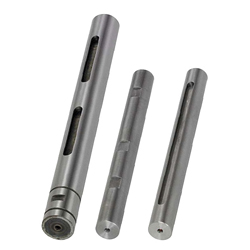
Motor shafts / machining selectable
Part Number
Once your search is narrowed to one product,
the corresponding part number is displayed here.
- Drawing / Specifications
- 3D Preview 3D preview is available after complete configuration
- Part Numbers
- More Information
- Catalog
- Technical Information
Dimensional Drawing

* For KZAF,  is
is  .
.
* KZAF may have a centering hole on the end face.
[!] Please note that D dimension tolerance of KZAF is different from that of KZAN, KZAC and KZAP.
| D | Tolerance | |
| h7 | h6 | |
| 10 | 0 -0.015 | 0 -0.009 |
| 12 | 0 -0.018 | 0 -0.011 |
| 15 | ||
| 17 | ||
| 20 | 0 -0.021 | 0 -0.013 |
| 25 | ||
| 30 | ||
| 35 | 0 -0.025 | 0 -0.016 |
| 40 | ||
| 45 | ||
| 50 | ||
| D | Circularity M | |
| Not Hardened | Hardened | |
| 10 | 0.004 | 0.003 |
| 12 | ||
| 15 | 0.005 | |
| 17 | ||
| 20 | ||
| 25 | 0.006 | 0.005 |
| 30 | ||
| 35 | ||
| 40 | ||
| 45 | 0.007 | |
| 50 | ||
| Type | D Tolerance | [M] Material | [H]Hardness | [S] Surface Treatment |
| KZAN | h7 | EN 1.1191 Equiv. | — | — |
| KZAC | Black Oxide | |||
| KZAP | Electroless Nickel Plating | |||
| KZAF | h6 | EN 1.1191 Equiv. | Induction Hardened | — |
| Surface Hardness 50HRC or more |
Specification Table
| Part Number | — | L |
| KZAN30 | — | 500 |
| Part Number | L | |
| Type | D | 0.5 mm Increments |
| KZAN KZAC KZAP KZAF | 10 | 50.0 to 300.0 |
| 12 | ||
| 15 | 100.0 to 400.0 | |
| 17 | ||
| 20 | ||
| 25 | 100.0 to 500.0 | |
| 30 | ||
| KZAF | 35 | |
| 40 | ||
| 45 | 200.0 to 500.0 | |
| 50 | ||
Alterations
| Part Number | — | L | — | (MA, NA, KA, TA, SC, WA, etc.) |
| KZAF40 | — | 450 | — | KA50 - HA100 - KB175 - HB100 |
| Alterations | Code | Spec. | |||||||||||||||||||||||||||||||||||||||||||||||||||||||||||||
| Left End | Right End | ||||||||||||||||||||||||||||||||||||||||||||||||||||||||||||||
Threaded Ends  | MA MSA MMA | MB MSB MMB | Adds threads at shaft ends. Specify the length of the threads. (Accuracy, coarse or fine threads differ depending on the current ordering code.)
[!]When D = M, thread length can be specified.
| ||||||||||||||||||||||||||||||||||||||||||||||||||||||||||||
Tapped Ends  | NA | NB | Adds taps on shaft ends. Select the thread diameter.
| ||||||||||||||||||||||||||||||||||||||||||||||||||||||||||||
Retaining Ring Groove  | TA | TB | Adds a retaining ring groove. Specify the position of a retaining ring groove. Ordering Code TA10-TB10 TA,TB = 1 mm Increments 4 ≤ TA (TB) [!] Retaining rings are included.
| ||||||||||||||||||||||||||||||||||||||||||||||||||||||||||||
Keyway Machining  | KA KB KC KD | Adds a keyway. Specify the position and the length of the keyway. Ordering Code KA10-HA30-KB100-HB50 KA, HA, KB, HB, KC, HC, KD, HD = 1 mm Increments [ ! ]3 ≤ HA,HB,HC,HD ≤ 100 [!]When more than 2 keyways are added, the tolerances may shift by up to 0.2°. | |||||||||||||||||||||||||||||||||||||||||||||||||||||||||||||
Keyway Machining + Set Screw Flat  | ZA ZB ZC ZD | Adds a flat at any designated angle based on the keyways. Specify the position and the length for each keyway, and the angle for the set screw flats. ·Specification Code
[!] The length of each set screw flat is the same as that of each keyway. | |||||||||||||||||||||||||||||||||||||||||||||||||||||||||||||
Wrench Flats  | SC | Adds wrench flats. Specify the position of a wrench flat.
| |||||||||||||||||||||||||||||||||||||||||||||||||||||||||||||
2 Set Screw Flats (Angle Specified)  | WA WB WC | Adds a flat at any designated angle besides the datum plane 0°. ·Specification Code
| |||||||||||||||||||||||||||||||||||||||||||||||||||||||||||||
·About KZAF (Induction Hardened)
When alterations on the above are specified,
the shafts are induction hardened after machining. (Except the threaded sections)
As a result, these may occur:
(1): Due to thermal conduction to the thread, the threads may be hardened by 2 to 3 mm. (2): Induction Hardened may shrink the keyway width (Around -0.01 to -0.02)
If the key becomes hard to fit, adjust it by gauging.
Part Number:
- In order to open the 3D preview, the part number must be fixed.
3D preview is not available, because the part number has not yet been determined.
| Part Number | Minimum order quantity | Volume Discount | RoHS | Hardness | Surface Treatment | Shaft Dia. D (mm) | Shaft Tolerance | L (mm) | |
|---|---|---|---|---|---|---|---|---|---|
| 1 | 9 Days | 10 | No Hardened | [Surface Treatment Provided] Black Oxide | 10 | h7 | 50 ~ 300 | ||
| 1 | 9 Days | 10 | No Hardened | [Surface Treatment Provided] Black Oxide | 12 | h7 | 50 ~ 300 | ||
| 1 | 9 Days | 10 | No Hardened | [Surface Treatment Provided] Black Oxide | 15 | h7 | 100 ~ 400 | ||
| 1 | 9 Days | 10 | No Hardened | [Surface Treatment Provided] Black Oxide | 17 | h7 | 100 ~ 400 | ||
| 1 | 9 Days | 10 | No Hardened | [Surface Treatment Provided] Black Oxide | 20 | h7 | 100 ~ 400 | ||
| 1 | 9 Days | 10 | No Hardened | [Surface Treatment Provided] Black Oxide | 25 | h7 | 100 ~ 500 | ||
| 1 | 9 Days | 10 | No Hardened | [Surface Treatment Provided] Black Oxide | 30 | h7 | 100 ~ 500 | ||
| 1 | 9 Days | 10 | No Hardened | [Surface Treatment Provided] Electroless Nickel Plating | 10 | h7 | 50 ~ 300 | ||
| 1 | 9 Days | 10 | No Hardened | [Surface Treatment Provided] Electroless Nickel Plating | 12 | h7 | 50 ~ 300 | ||
| 1 | 9 Days | 10 | No Hardened | [Surface Treatment Provided] Electroless Nickel Plating | 15 | h7 | 100 ~ 400 | ||
| 1 | 9 Days | 10 | No Hardened | [Surface Treatment Provided] Electroless Nickel Plating | 17 | h7 | 100 ~ 400 | ||
| 1 | 9 Days | 10 | No Hardened | [Surface Treatment Provided] Electroless Nickel Plating | 20 | h7 | 100 ~ 400 | ||
| 1 | 9 Days | 10 | No Hardened | [Surface Treatment Provided] Electroless Nickel Plating | 25 | h7 | 100 ~ 500 | ||
| 1 | 9 Days | 10 | No Hardened | [Surface Treatment Provided] Electroless Nickel Plating | 30 | h7 | 100 ~ 500 |
Loading...
Specifications/Overview
■Selection of Driving Shaft
In selecting a driving shaft, select the basic shape and size from the specification table, then select necessary alterations such as thread machining, keyway addition etc.
[Selection Example of Part Number]
·Alteration Selection: Keyways at Two Locations

[!] The example below shows the keyway shape under the following conditions:
When KA, KB, KC, KD, ZA, ZB, ZC, ZD = 0
KA+HA·KB+HB·KC+HC·KD+HD·ZA+HA·ZB+HB·
When ZC + HC, ZD + HD = L

[App. Example]

Basic information
| Basic Shape | Straight | Material | EN 1.1191 Equiv. |
|---|
Configure
Basic Attributes
-
Hardness
- No Hardened
-
Shaft Dia. D(mm)
-
Shaft Tolerance
- h6
- h7
-
L(mm)
-
Type
- KZAC
- KZAF
- KZAN
- KZAP
-
Surface Treatment
- No Surface Treatment
- Surface Treatment Provided
-
Filter by CAD data type
- 2D
- 3D
Filter by standard shipping days
-
- All
- 9 Days or Less
- 18 Days or Less
Optional Attributes
- The specifications and dimensions of some parts may not be fully covered. For exact details, refer to manufacturer catalogs .
Complementary Products
-
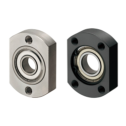 Bearing housings / compact flange / through holes / circlip / deep groove ball bearing / steel, stainless steel / black oxide, nickel plated
MISUMI Standard Price : 19.64 € Shipping Days: 9 Days
-
 Slot nut / steel / black oxided / adjusting tip phosphor bronze / precision class selectable
MISUMI Standard Price : 14.48 € Shipping Days: Same day
-
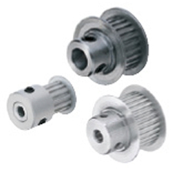 Timing belt pulleys / MXL / flanged pulley selectable / configurable / material selectable / treatment selectable
MISUMI Shipping Days: 6 Days
-
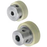 Track rollers with PUR tread / with holes for fixing screw
MISUMI Standard Price : 11.26 € Shipping Days: 5 Days


Tech Support
- Technical Support
- Tel:+49 69 668173-0 / FAX:+49 69 668173-360
- Technical Inquiry
Payment Method


On-Demand Manufacturing
Certificates


Copyright © MISUMI Corporation All Rights Reserved.