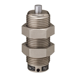
Shock Absorbers / Compact
- Volume Discount
- Order quantities extended (D-JIT)
Part Number
Once your search is narrowed to one product,
the corresponding part number is displayed here.
- Drawing / Specifications
- 3D Preview 3D preview is available after complete configuration
- Part Numbers
- Catalog
Dimensional Drawing

[ ! ] Collision velocity range: 0.3 to 1 m/s
[ ! ] Max. operating cycle: 60 cycle/min
[ ! ] Impact force can be easily adjusted by turning the flat head screwdriver adjusting slot.
[S] Surface Treatment: Electroless Nickel Plating
Specification Table
| Part Number |
| MAMS2006 MAMKS2508 |
| Part Number | Thread Dia. | Stroke | Maximum Absorbed Energy (E') | Maximum Equivalent Mass (me') (kg) | Piston Rod Return Force (N) | Max. Drag Value (N) | (L1) | (L2) | d1 | f | B (Wrench Flats) | T | ||
| Type | No. | M × P | S | Per cycle (J) | Per minute (J) | |||||||||
| MAMS | 1406 | M14 × 1.5 | 6 | 3.5 | 100 | 80 | 15 | 2,000 | 41 | 8 | 4 | 2 | 19.6 (17) | 6 |
| 1606 | M16 × 1.5 | 4.8 | 130 | 120 | 20 | 2,700 | 5 | 21.9 (19) | ||||||
| 2006 | M20 × 1.5 | 7.8 | 200 | 60 | 16.7 | 3,920 | 43 | 6 | 6 | 1.5 | 27.7 (24) | 8 | ||
| 2506 | M25 × 1.5 | 11.7 | 300 | 90 | 19.6 | 5,880 | 8 | 37 (32) | 10 | |||||
| 2706 | M27 × 1.5 | 15.6 | 350 | 120 | 22.6 | 7,840 | ||||||||
- [Maximum Drag Value]The maximum value of the hydraulic resistance force that occurs during energy absorption (during stroke).
- [Maximum Absorbed Energy]The maximum amount of energy that the absorber can receive at one time. (More than this will lead to damage)
- [Equivalent Mass]The mass when the total energy to be absorbed by the absorber is equivalent to the kinetic energy in horizontal motion.
It is "a value that converts selected factors such as thrust, the amount of collision material, and velocity into mass." - [Piston Return Force]This is the spring force that causes the piston to return from its pushed position.
Selection Supporting Information
■Oil shock absorber is a shock absorber that primarily uses oil.
Compared with other cushioning materials (rubber, spring, air, etc.), they are compact and capable of repeatedly absorbing large impact energy softly without rebound.
Internal structure and basic principle of oil type shock absorbers are shown as follows.
When an object collides with a piston rod, the oil in the pressure chamber is compressed by a piston.
The clearance between inner tube and piston is so small that compressed oil is forced out of the orifices.
At this point, the impact energy is converted into heat energy by dynamic resistance.
This mechanism provides an ideal shock absorbing action.
Various absorption characteristics can be obtained depending on the number and size of orifices.
(Refer to classification according to absorption characteristics structures.)
Please note that when the wrong collision speed is selected, some abnormal reaction may occur during collision or the impact energy may not be absorbed in an ideal manner.

■Procedure of Selection
·moment of inertia (I) and collision angular velocity (ω).
additional energy according to Examples Of Calculation For Selection.
| Calculate the temporary stroke S' with the Inertial Energy E1 (Adjustable / Fixed Force Type)  Fig. 2 Select the orifice type from energy ratio (additional energy E2' / inertial energy E1)  |
Examples of Calculation for Selection | Selection examples: Pure inertia collision (Horizontal collision without thrust) | Selection examples: Horizontal collision with air cylinder thrust force | Selection examples: Non-thrust stop when cylinder descends | |||||||||
App. Example and Collision Conditions |
[Collision Conditions] |
[Collision Conditions] |
[Collision Conditions] Air Cylinder | |||||||||
Collision Velocity V | [m/s] | V = 0.6 m/s | V = 0.6 m/s | V = 0.2 m/s * Collision velocity V is actual measurements | ||||||||
Absorbed Energy | Moment of Inertia | [J] | E1 = m × V22 = 25 × 0.622 = 4.5 J | E1 = m × V2 2 = 30 × 0.62 2 = 5.4 J | E1 = m × V2 2 = 15 × 0.22 2 = 0.3 J | |||||||
Temporary stroke S' | [mm] | From Figure 1, S' = 20 mm (Select adjustable type) | From Figure 1, S' = 15 mm (Select adjustable type) | From Figure 1, S' = 10 mm (Select adjustable type) | ||||||||
Additional Energy E2 | [J] | E2’ = 0J | Thrust of the cylinder is F = 628.4N E2' = F × S' = 628.4 × 0.015 = 14.8 J | Cylinder thrust is F = 245.4 N E2' = (F + mg) × S' = (245.4 + 15 × 9.8) × 0.01 = 3.92 J | ||||||||
Total energy E' | [J] | E’ = E1+E2’ = 4.5+0 = 4.5J | E’ = E1+E2’ = 5.4+9.4 = 14.8J | E’ = E1+E2’ = 0.3+3.92 = 4.22J | ||||||||
Equivalent Mass me' | [kg] | me' = 2 × E' V2 = 2 × 4.5 0.62 = 25 kg | me' = 2 × E' V2 = 2 × 14.8 0.62 = 82.2 kg | me' = 2 × E' V2 = 2 × 4.22 0.22 = 211 kg | ||||||||
Tentative selection | Select Adjustable Type Select L from the collision velocity. Select MAC1612 from E and me' | (stroke S = 12 mm) | Select Adjustable Type Select medium speed M from the collision velocity. Select MAC2016M from E and me' | (stroke S = 16 mm) | Select Adjustable Type Select ultra low speed S from Fig. 2. Select MAC1612S from E and me' | (stroke S = 12 mm) | ||||||
Recalculation | E2 = 0J E = E1+E2 = 4.5J | me = 2 × E V2 = 25 kg | E2+F × S=10.1J E = E1+E2 = 15.5J | me = 2 × E V2 = 86.1 kg | E2 + (F + mg) × S = 4.71 J E = E1+E2 = 0.3+4.71=5.01J | me = 2 × E V2 = 250 kg | ||||||
Energy per minute ET | ET = E × N = 4.5 × 30 = 135 J/min | ET = E × N = 15.5 × 20 = 310 J/min | ET = E × N = 5.01 × 10 = 50.1 J/min | |||||||||
Confirmation | E, me, N, and ET are all OK Select MAC1612L | E, me, N, and ET are all OK Select MAC2016M | E, me, N, and ET are all OK Select MAC1612S | |||||||||


Examples of Calculation for Selection | Selection examples: Horizontal collision with belt conveyor thrust force | Selection examples: Collision with synchronous motor driven load | Selection examples: Horizontal rotation collision with torque | ||||||||
App. Example and Collision Conditions |
[Collision Conditions] |
[Collision Conditions] |
[Collision Conditions] | ||||||||
Collision Velocity V | [m/s] | V = 0.5m/s | V = Rω = 0.40 × 5.6 = 2.24 m/s | V = Rω = 1.25 × 1.8 = 2.25 m/s | |||||||
Absorbed Energy | Moment of Inertia Energy E1 | [J] | E1 = m × V22 = 5 × 0.522 = 0.625 J | E1=Iω22=0.12 × 5.622=1.88J | E1=Iω22=125.5 × 1.822=203.31J | ||||||
Temporary stroke S' | [mm] | From Figure 1, S' = 5 mm (Select adjustable type) | From Figure 1, S' = 10 mm (Select adjustable type) | From Figure 1, S' = 50 mm (Select adjustable type) | |||||||
Additional Energy E2 | [J] | F = µmg = 0.4 × 5 × 9.8 = 19.6 N E2’ = F·S’ = 19.6 × 0.005 = 0.098J | E2' = (F + mg) × S' = (59.3 + 1 × 9.8) × 0.01 = 0.69 J | E2’=TR·S’=68.61.25 × 0.05=2.74J | |||||||
Total energy E' | [J] | E’ = E1+E2’ = 0.625+0.098 = 0.723J | E’ = E1+E2’ = 1.88+0.69 = 2.57J | E’ = E1+E2’ = 203.31+2.74 = 206.05J | |||||||
Equivalent Mass me' | [kg] | me' = 2 × E'V2 = 2 × 0.723 0.52 = 5.8 kg | me'= 2 × E'V2 = 2 × 2.57 2.242 = 1.0 kg | me'= 2 × E'V2 = 2 × 206.05 2.252 = 81.4 kg | |||||||
Tentative selection | Select Fixed Force Type Select Single Orifice from V Select MAKC1005 B from E' and me' | (stroke S = 5 mm) | Select Adjustable Type Select Multi-Orifice from Fig. 2. Select MAC1210H from E' and me' | (stroke S = 10 mm) | Select Adjustable Type Select Speed H Type from Fig. 2. Select MAC3650H from E' and me' | (stroke S = 50 mm) | |||||
Recalculation | E2 = E2’ = 0.098J E = E1+E2 = 0.723J | me = 2 × EV2 = 5.8 kg | E2 = 0.69J E = E1+E2 = 2.57J | me = 1.0 kg | E2=TR·S=2.74J E=E1+E2=206.05J | me = 2 × E V2 = 81.4 kg | |||||
Energy per minute ET | ET = E × N = 0.723 × 20 = 14.46 J/min | ET = E × N = 2.57 × 10 = 25.7 J/min | ET = E × N = 206.05 × 6 = 1,236.3 J/min | ||||||||
Confirmation | E, me, N, and ET are all OK Select MAKC1005 B | E, me, N, and ET are all OK Select MAC1210H | E, me, N, and ET are all OK Select MAC3650H | ||||||||


Structure | Adjustable | Fixed Force Type | |||
Tapered orifice | S Type A Type B Type L Type |  | There are three types of tapered orifices; a dashpot structure using a clearance between the piston and cylinder tube, a single-tube structure with an orifice in the piston, and a double-tube type tapered orifice, all of which exhibit similar drag force characteristics. The piston slides in a cylinder tube filled with oil, and a tapered orifice is installed in this piston. Because the orifice area is constant over the entire stroke, as the shock absorption characteristics shown in the right graph, the resistance is the largest immediately after a collision but gradually reduces speed as the stroke continues. |  | |
Irregular Multi Orifice | Medium Speed Type M |  | In this double-tube structure, the piston slides the inner wall of the inner tube. This inner tube has several orifices along the direction of strokes, and not constant damping, but absorbs energy depending on various purposes. It is designed to absorb kinetic energy during the first half of stroke and control speed during the second half. Therefore, it is well suited to absorb energy against air cylinder thrust. |  | |
Multi Orifice | High Speed Type H |  | In this double-tube structure, the piston slides in the inner tube. This inner tube has several orifices along the direction of strokes. Because the orifice area becomes small gradually as the stroke speed slows down, the drag force fractures but the maximum drag is lower. |  | |
E = E'/n
E: Energy acting on each shock absorber
E’: Total Energy
n: Number of shock absorber receivers
* Do not use adjustable type shock absorbers in parallel.
App. Example
 |  |
- The shock absorber cannot be used at full stroke.
If used at full stroke, there is a possibility of damage. - Install so that the object stops at a distance of 1 mm or more from the stroke end, or install an external stopper as required.
Stopper nuts also can be used.

Cautions on Use
- Shock absorbers use oil internally, and seals are used to prevent oil from leaking to the outside, but a perfect seal cannot be guaranteed.
Because of this, it cannot be used in environments that prohibit oil. - Check for oil leaks and the return status of the piston rod. If leaking of a large amount of oil or failure of returning piston rod are found, there
may be some abnormality and it should be replaced. If you use a defective product, it may cause damage to the unit to which it is installed. - With the number of uses, the energy absorption capacity will decrease due to the reduction in internal oil and wear of parts. Taking this into account, we recommend selecting a size that has at least 20 to 40% margin for the maximum absorbed energy.
- The performance and functionality of shock absorbers may deteriorate depending on the load. Perform daily inspections to ensure that the required functions are met and to prevent accidents from occurring.
- For types with analog adjustment scales, first set the adjustment knob roughly to a position "between 1 and 2" and see how collisions are. Then readjust the scale to set it to the optimal position.
(Characteristics: Weak) 1 ← 2 → 3 (Characteristics: Strong), (Characteristics: Weak) 1 ← → 7 (Characteristics: Strong)

- *) During adjustment, be sure to protect the shock absorber with an external stopper or stopper nut. Be sure to tighten the lock screw when the adjustment is complete.
If the product is used without being locked, the adjustment knob will rotate idly, so proper shock absorption performance cannot be obtained.
However, some types do not have a lock screw mechanism. (See below.)
If a type without a lock screw mechanism is used, the adjusting shaft will not rotate during normal use, but if it is used in a place where vibration occurs,
the adjusting shaft could rotate. Please check this point with the actual device before deciding whether or not the target product can be used.
*No lock screw mechanism: MAC/MAS/MACC/MACS 0806/1008/1210 series
Part Number:
- In order to open the 3D preview, the part number must be fixed.
3D preview is not available, because the part number has not yet been determined.
Part Number
|
|---|
| MAMS1406 |
| MAMS1606 |
| MAMS2006 |
| MAMS2506 |
| MAMS2706 |
| Part Number |
Standard Unit Price
| Minimum order quantity | Volume Discount | RoHS | Mounting Screw Nominal (M) | Max. Absorbed Energy (J) | Equivalent Mass (kgf) | Max. Resisting Force Value (N) | Piston Rod Return Force (N) | Max. Absorbed Energy (per Minute) (J/min) | Thread Size M | |
|---|---|---|---|---|---|---|---|---|---|---|---|---|
80.60 € | 1 | Available | 5 Days | 10 | M14 | 3.5 | 80 | 2000 | 15 | 100 | M14X1.5 | |
85.63 € | 1 | Available | 5 Days | 10 | M16 | 4.8 | 120 | 2700 | 20 | 130 | M16X1.5 | |
88.16 € | 1 | Available | 5 Days | 10 | M20 | 7.8 | 60 | 3920 | 16.7 | 200 | M20X1.5 | |
100.74 € | 1 | Available | 5 Days | 10 | M25 | 11.7 | 90 | 5880 | 19.6 | 300 | M25X1.0 | |
113.35 € | 1 | Available | 5 Days | 10 | M27 | 15.6 | 120 | 7840 | 22.6 | 350 | M27X1.5 |
Loading...
Basic information
| Main Body, Related Components | Main Body | Structure | Compact Adjustable | Stroke(mm) | 6 |
|---|---|---|---|---|---|
| Orifice Type | Tapered orifice | Usage Environment | Standard | Main Body Material | JIS-SUM Free Cutting Steel |
| Max. Collision Velocity(m/s) | 1 | Min. Collision Velocity(m/s) | 0.3 | Max. Operating Cycle(cycle/min) | 60 |
| Operating Temperature Range(°C) | -5::70 |
Configure
Basic Attributes
-
Max. Absorbed Energy(J)
-
Equivalent Mass(kgf)
-
Max. Resisting Force Value(N)
-
Piston Rod Return Force(N)
-
Max. Absorbed Energy (per Minute)(J/min)
-
Thread Size M
-
Type
- MAMS
-
Filter by CAD data type
- 2D
- 3D
Filter by standard shipping days
-
- All
- 5 Days or Less
Optional Attributes
- The specifications and dimensions of some parts may not be fully covered. For exact details, refer to manufacturer catalogs .
Complementary Products
-
 Linear ball bearings / block shape / aluminium / anodised
MISUMI Standard Price : 11.62 € Shipping Days: Same day
-
 Profile rail guideways / carriage dimensions selectable / high quality / heavy-duty version
MISUMI Shipping Days: 7 Days
-
 Ball screws / block nut / diameter 15, 20, 25 / pitch 5, 10 / C10 / steel / phosphated / 58-62HRC
MISUMI Shipping Days: 7 Days


Tech Support
- Technical Support
- Tel:+49 69 668173-0 / FAX:+49 69 668173-360
- Technical Inquiry
Payment Method


On-Demand Manufacturing
Certificates


Copyright © MISUMI Corporation All Rights Reserved.