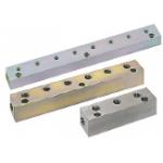
Manifold Hydraulic / Outlets 1 Side / 2 Inlets
- Order quantities extended (D-JIT)
Part Number
Once your search is narrowed to one product,
the corresponding part number is displayed here.
- Drawing / Specifications
- 3D Preview 3D preview is available after complete configuration
- Part Numbers
- Catalog

● Standard Hole Shape
Front Surface Counterbore

| Mounting Hole Dimension | d | D | h | D1 | d1 | h1 |
| M5 | 5.5 | 9.5 | 5.5 | 8 | *4.2 | 4.5 |
| M6 | 6.6 | 11 | 6.5 | 9.5 | 5.1 | 5.5 |
| M8 | 8.5 | 14 | 8.5 | 11 | 6.8 | 6.5 |
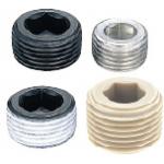
● Mounting Hole Change
Back Surface Counterbore (ZB)
Through Hole (NA)
Tapped Hole (T)
Counterbore Tapped Hole (ZT)

JIS B0203 Rc (PT) JIS B0202 G (PF): ISO 228-1 Interchangeable
ANSI/ASME B.I.20.1-1983 (NPT)
* Drawing for 3 Circuit Type is selected. The total number of Q, G and K threads is 5.
[ ! ] X dimension for 30 × 35 Sq. 1 Circuit Type is 15.
[ ! ] Mounting hole shape can be selected freely.
[ ! ] Standard hole shape is selected when no hole shape modification is specified.
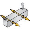
[L Dimension Calculation]
Example: For BMBFP3- to -P35
L = N × P + 2E = (Number of stations 3-1) × 35 + 2 × 25 = 120
| Type | [M] Material | [S] Surface Treatment | Max. Operating Pressure | ||||||
| Pitch (P) Standard | Pitch (P) Configurable | ||||||||
| 25 × 32 Sq. | 30 × 35 sq. | 50 Sq. | 60 sq. | 25 × 32 Sq. | 30 × 35 sq. | 50 Sq. | |||
| BMBS | BMBF | BMBFL | BMBL | BMBSP | BMBFP | BMBFLP | Steel for General Structure | Trivalent Chromate | 20.6 MPa ≈ 210 kgf/cm2 or less |
| — | BMBFM | BMBFLM | — | — | BMBFMP | BMBFLMP | Electroless Nickel Plating | ||
| BMBSR | BMBFR | BMBFLR | — | BMBSRP | BMBFRP | BMBFLRP | EN 1.4301 Equiv. | — | |
| — | BMBFS | — | — | — | BMBFSP | — | EN 1.4401 Equiv. | ||
| — | BMBFC | — | — | — | — | — | Brass | 1 MPa ≈ 10 kgf/cm2 or less | |
Part Number:
- In order to open the 3D preview, the part number must be fixed.
3D preview is not available, because the part number has not yet been determined.
| Part Number | Minimum order quantity | Volume Discount | RoHS | Shape | Material | Surface Treatment | Block Size (mm) | Number of Circuits (Circuits) | Thread Size / Type | Mounting Hole Change | Pitch P (mm) | Pitch Standard / Configurable | Application | Drawing G Part Thread Dia. NPT Selection [G] | Drawing K Part Thread Dia. NPT Selection [K] | Drawing Q Part Thread Dia. NPT Selection [Q] | Select a value for PT/PF Thread Dia. on G (in Drawing). [G] 1(1/8) 2(1/4) 3(3/8) 4(1/2) 6(3/4) 8(1) | Select a value for PT/PF Thread Dia. on K (in Drawing). [K] 1(1/8) 2(1/4) 3(3/8) 4(1/2) 6(3/4) 8(1) | Select a value for PT/PF Thread Dia. on Q (in Drawing). [Q] 1(1/8) 2(1/4) 3(3/8) 4(1/2) 6(3/4) 8(1) | |
|---|---|---|---|---|---|---|---|---|---|---|---|---|---|---|---|---|---|---|---|---|
| 1 | 7 Days | 10 | Vertical Through Hole | Brass | Not Provided | 30 x 35 | 6 | G (PF) Thread | ZT (Counterbore Tapped) | 40 | Fixed Type | For Oil, Water Hydraulic | - | - | - | 2 ~ 4 | 2 ~ 4 | 1 ~ 3 | ||
| 1 | 9 Days | 10 | Vertical Through Hole | EN 1.0038 Equiv. | Trivalent Chromate | 50 x 50 | 6 | G (PF) Thread | ZT (Counterbore Tapped) | 35 ~ 60 | Configurable Type | For hydraulic / Water Pressure | - | - | - | 2 ~ 6 | 2 ~ 6 | 2 ~ 6 | ||
| 1 | 9 Days | 10 | Vertical Through Hole | EN 1.4301 Equiv. | Not Provided | 50 x 50 | 6 | G (PF) Thread | ZT (Counterbore Tapped) | 35 ~ 60 | Configurable Type | For Water Hydraulic | - | - | - | 2 ~ 6 | 2 ~ 6 | 2 ~ 6 | ||
| 1 | 9 Days | 10 | Vertical Through Hole | Steel for General Structure | Electroless Nickel Plating | 30 x 35 | 8 | G (PF) Thread | ZT (Counterbore Tapped) | 40 | Fixed Type | For hydraulic / Water Pressure | - | - | - | 2 ~ 4 | 2 ~ 4 | 1 ~ 3 |
Loading...
Configure
Basic Attributes
-
Material
- EN 1.0038 Equiv.
- EN 1.4301 Equiv.
- EN 1.4401 Equiv.
- Brass
- Steel for General Structure
-
Surface Treatment
- Not Provided
- Trivalent Chromate
- Electroless Nickel Plating
-
Block Size(mm)
- 25 x 32
- 30 x 35
- 50 x 50
- 60 x 60
-
Number of Circuits(Circuits)
- 1
- 2
- 3
- 4
- 5
- 6
- 7
- 8
-
Thread Size / Type
-
Mounting Hole Change
- NA (Through)
- Not Specified (Front Surface Counterbore)
- T (Tapped)
- ZB (Back Surface Counterbore)
- ZT (Counterbore Tapped)
-
Pitch P(mm)
-
Pitch Standard / Configurable
- Configurable Type
- Fixed Type
-
Application
- For Oil, Water Hydraulic
- For Water Hydraulic
- For hydraulic / Water Pressure
-
Drawing G Part Thread Dia. NPT Selection [G]
- 1/2 [G4N]
- 1/4 [G2N]
- 1/8 [G1N]
- 3/8 [G3N]
-
Drawing K Part Thread Dia. NPT Selection [K]
- 1/2 [K4N]
- 1/4 [K2N]
- 3/8 [K3N]
-
Drawing Q Part Thread Dia. NPT Selection [Q]
- 1/4 [Q2N]
- 1/8 [Q1N]
- 3/8 [Q3N]
-
Select a value for PT/PF Thread Dia. on G (in Drawing). [G] 1(1/8) 2(1/4) 3(3/8) 4(1/2) 6(3/4) 8(1)
-
Select a value for PT/PF Thread Dia. on K (in Drawing). [K] 1(1/8) 2(1/4) 3(3/8) 4(1/2) 6(3/4) 8(1)
-
Select a value for PT/PF Thread Dia. on Q (in Drawing). [Q] 1(1/8) 2(1/4) 3(3/8) 4(1/2) 6(3/4) 8(1)
-
Type
- BMBF
- BMBFC
- BMBFL
- BMBFLM
- BMBFLMP
- BMBFLP
- BMBFLR
- BMBFLRP
- BMBFM
- BMBFMP
- BMBFP
- BMBFR
- BMBFRP
- BMBFS
- BMBFSP
- BMBL
- BMBS
- BMBSP
- BMBSR
- BMBSRP
- G-BMBF
- G-BMBFC
- G-BMBFL
- G-BMBFLM
- G-BMBFLMP
- G-BMBFLP
- G-BMBFLR
- G-BMBFLRP
- G-BMBFM
- G-BMBFMP
- G-BMBFP
- G-BMBFR
- G-BMBFRP
- G-BMBFS
- G-BMBFSP
- G-BMBL
- G-BMBS
- G-BMBSP
- G-BMBSR
- G-BMBSRP
-
Shape
-
 Vertical Through Hole
 -
 Blind Lateral Hole, Upper Hole
-
-
Filter by CAD data type
- 2D
- 3D


Filter by standard shipping days
-
- All
- 6 Days or Less
- 7 Days or Less
- 9 Days or Less
- 11 Days or Less
Optional Attributes
- The specifications and dimensions of some parts may not be fully covered. For exact details, refer to manufacturer catalogs .
Complementary Products
-
 Fitting for Hydraulic Pressure / Water Pressure, Long Straight Type, Male Thread for Both PT / PF, -Long Straight / Female-
MISUMI Standard Price : 13.10 € Shipping Days: 5 Days
-
 Hydraulic Fittings / 90 Deg. Elbow / PT Threaded / PF Tapped
MISUMI Standard Price : 7.67 € Shipping Days: Same day
-
 Swivel Joints / Straight / 90 Deg. Elbow / PT Threaded / PT / PF Tapped / Threaded
MISUMI Standard Price : 32.74 € Shipping Days: 5 Days


Tech Support
- Technical Support
- Tel:+49 69 668173-0 / FAX:+49 69 668173-360
- Technical Inquiry
Payment Method


On-Demand Manufacturing
Certificates


Copyright © MISUMI Corporation All Rights Reserved.