Timing belt connecting plates / XL, L, T5, S#M / aluminium (Part Numbers - CAD Download)

Part Number
Once your search is narrowed to one product,
the corresponding part number is displayed here.
- Drawing / Specifications
- 3D Preview 3D preview is available after complete configuration
- Part Numbers
- More Information
- Catalog
- Technical Information

■ Accuracy Standards
● Flatness: 0.4 or Less per 1,000 mm
● Tolerance of Plate Thickness ±0.04 for 6
±0.05 for 8

[ ! ]A groove for overpressure prevention is provided to prevent a belt from being excessively clamped.

| Recommended Combinations | ||
| Type | Belt Type | Applicable Linear Guide |
| TBLG | S3M | Miniature Linear Guides |
| S5M | Miniature Linear Guides Linear Guides for Medium Load | |
| T5 | ||
| XL | ||
| L | Linear Guides for Medium Load Linear Guides for Heavy Load | |
| S8M | ||
| Counterbored Hole | |||||||||||||||||||||||||||||||||||||||||||
| Z·Z1 | |||||||||||||||||||||||||||||||||||||||||||
 Z1 Counterbore Dimension on Belt Mounting Side
Z: Counterbore Dimension on Guide Pushing Side
| |||||||||||||||||||||||||||||||||||||||||||
| Type | [M] Material | [S] Surface Treatment | Number of Workpiece Mounting Holes |
| TBLG | EN AW−5052 Equiv. | Clear Anodize | 6 |
| [A] Accessory | [M] Material | Qty. |
| Timing Belt Clamp Plates | EN AW−6061 Equiv. | 1 |
| Extra Low Head Cap Screw (for Belt Mounting): CBSTS | EN 1.4301 Equiv. | 4 |
Specification Table
1.: Specify the type and width of belt.
2.: Specify the A dimension (plate width), L dimension (center distance between Linear Guide and Timing Belt) and S dimension (Depth of Clamp Plate toward the Linear Guide Center).
3.: Specify the B/C dimension (mounting hole pitch for Linear Guide) and the Z dimension (counterbore nominal dia. for Linear Guide-mounting screw). Specify the hex socket head cap screw to fit the mounting hole (counterbored hole) of Linear Guide.
[ ! ] Linear Guide-mounting screws are not included.
Ordering Example
| Part Number | — | A | — | L | — | S | — | B | — | C | — | Z |
| TBLGXL050 | — | 50 | — | 100 | — | 24 | — | 35 | — | 35 | — | 6 |
| Type | Applicable belts | Dimension Configurable (1 mm Increments) | Fixed Dimension | |||||||||||||||
| Plate | Linear Guide-mounting Hole | Guide Side | Belt Side | |||||||||||||||
| Belt Type | Nominal Width | A | L | S | B | C | Z (Counterbored Hole) | T | M (Tapped Hole) | P | G | K | Z1 (Counterbored Hole) Screw Nominal | T1 | (Referential Info) Belt Width | |||
| TBLG | XL | 025 | 36 to 90 | 50 to 250 | 11 to 45 | 12 to 60 | 12 to 50 | 3·4·5·6 | T: 6 (Z=3·4 selected) T: 8 (Z=5·6 selected) | M=Z | 13 | 25 | 12 | 4 | 2.1 | 6.4 | ||
| 031 | 14 | 12.5 | 7.9 | |||||||||||||||
| 037 | 16 | 13 | 9.5 | |||||||||||||||
| 050 | 20 | 15 | 12.7 | |||||||||||||||
| L | 050 | 66 to 125 | 55 to 250 | 15 to 45 | 17 to 60 | 17 to 50 | 5·6 | 21 | 50 | 16 | 5 | 3.3 | 12.7 | |||||
| 075 | 27 | 19 | 19.1 | |||||||||||||||
| 100 | 34 | 23 | 25.4 | |||||||||||||||
| 150 | 46 | 29 | 38.1 | |||||||||||||||
| S3M | 060 | 25 to 90 | 30 to 150 | 11 to 45 | 12 to 28 | 12 to 35 | 3·4·5·6 | 11 | 15 | 10 | 3 | 1.9 | 6 | |||||
| 100 | 15 | 12.5 | 10 | |||||||||||||||
| 150 | 20 | 15 | 15 | |||||||||||||||
| S5M | 100 | 37 to 100 | 50 to 250 | 15 to 45 | 17 to 60 | 17 to 50 | 5·6 | 17 | 25 | 13 | 4 | 3.1 | 10 | |||||
| 150 | 22 | 16 | 15 | |||||||||||||||
| 250 | 32 | 21 | 25 | |||||||||||||||
| S8M | 150 | 56 to 150 | 60 to 250 | 15 to 45 | 17 to 60 | 17 to 50 | 5·6 | 23 | 40 | 17 | 5 | 4.7 | 15 | |||||
| 250 | 33 | 22 | 25 | |||||||||||||||
| 300 | 38 | 25 | 30 | |||||||||||||||
| 400 | 48 | 30 | 40 | |||||||||||||||
| T5 | 100 | 35 to 100 | 50 to 250 | 11 to 45 | 12 to 60 | 12 to 50 | 3·4·5·6 | 17 | 25 | 13 | 4 | 2.2 | 10 | |||||
| 150 | 22 | 16 | 15 | |||||||||||||||
| 200 | 27 | 19 | 20 | |||||||||||||||
| 250 | 32 | 21.5 | 25 | |||||||||||||||
| [ ! ]W=L+K+S [ ! ] AC - Zd1 ≥ 2 [ ! ] L-B-P/2-Z1 d1/2-M/2 ≥ 1 | [ ! ] B (C)-Zd1-M ≥ 2 [ ! ] SB/2-Zd1/2 ≥ 1 [ ! ]L ≥ A | |||||||||||||||||
| Accessory | |||||||||||
| Timing Belt Clamp Plates | Extra Low Head Cap Screw | ||||||||||
| Belt Type | Nominal Width | Belt Width | AT | BT | TT | h | P | G | M | For T = 6 | For T = 8 |
| XL | 025 | 6.4 | 36 | 24 | 6 | 1.30 | 13 | 25 | M4 | CBSTS4-10 | CBSTS4-12 |
| 031 | 7.9 | 25 | 14 | ||||||||
| 037 | 9.5 | 26 | 16 | ||||||||
| 050 | 12.7 | 30 | 20 | ||||||||
| L | 050 | 12.7 | 66 | 32 | 8 | 2.05 | 21 | 50 | M5 | - | CBSTS5-12 |
| 075 | 19.1 | 38 | 27 | ||||||||
| 100 | 25.4 | 46 | 34 | ||||||||
| 150 | 38.1 | 58 | 46 | ||||||||
| S3M | 060 | 6 | 21 | 18 | 4 | 1.25 | 11 | 15 | M3 | CBSTS3-8 | CBSTS3-10 |
| 100 | 10 | 22 | 15 | ||||||||
| 150 | 15 | 28 | 20 | ||||||||
| S5M | 100 | 10 | 35 | 26 | 6 | 2.00 | 17 | 25 | M4 | - | CBSTS4-12 |
| 150 | 15 | 32 | 22 | ||||||||
| 250 | 25 | 42 | 32 | ||||||||
| S8M | 150 | 15 | 56 | 34 | 8 | 3.00 | 23 | 40 | M5 | CBSTS5-14 | |
| 250 | 25 | 44 | 33 | ||||||||
| 300 | 30 | 50 | 38 | ||||||||
| 400 | 40 | 60 | 48 | ||||||||
| T5 | 100 | 10 | 35 | 26 | 6 | 1.40 | 17 | 25 | M4 | CBSTS4-10 | CBSTS4-12 |
| 150 | 15 | 32 | 22 | ||||||||
| 200 | 20 | 38 | 27 | ||||||||
| 250 | 25 | 43 | 32 | ||||||||
Alterations
| Alterations Code | Alteration Details | Application Notes | Ordering Example | |||||||||||
| MH | Changes the Tapped Hole Dia. on the Linear Guide Mounting Side | Change the Tapped Hole Dia. from Z (Counterbore Nominal Dia.) = M. [Ordering Code]MH3
| "!" When MH and MT are combined: MT is applied to 2 places on the plate center. MH is applied to 4 places on portions other than Plate Center. [ ! ] B (C)-Zd1-MH ≥ 2 | TBLGXL050-50-100-24-35-35-6-MH4 | ||||||||||
| MT | Changes the dia. of each of two tapped holes on the Plate Center | Out of 6 tapped holes on Linear Guide Mounting Side, 2 tapped holes located on Plate Center are changed to the other hole dia. [Ordering Code]: MT2
| "!" When MH and MT are combined: MT is applied to 2 places on the plate center. MH is applied to 4 places on portions other than Plate Center. [ ! ] B (C)-Zd1-MT ≥ 2 | TBLGXL050-50-100-24-35-35-6-MT2 | ||||||||||
Part Number:
- In order to open the 3D preview, the part number must be fixed.
3D preview is not available, because the part number has not yet been determined.
| Part Number | Minimum order quantity | Volume Discount | RoHS | Belt Type | Belt Width (mm) (mm) | Belt Width (Inch) (Inch) | A (mm) | B (mm) | C (mm) | L (mm) | S (mm) | Z | |
|---|---|---|---|---|---|---|---|---|---|---|---|---|---|
| 1 | 9 Days | 10 | T5 | 10 | 1 | 35 ~ 100 | 15 ~ 60 | 12 ~ 50 | 50 ~ 250 | 17 ~ 45 | 3 ~ 6 | ||
| 1 | 9 Days | 10 | T5 | 15 | 1.5 | 35 ~ 100 | 15 ~ 60 | 12 ~ 50 | 50 ~ 250 | 17 ~ 45 | 3 ~ 6 | ||
| 1 | 9 Days | 10 | T5 | 20 | 2 | 35 ~ 100 | 15 ~ 60 | 12 ~ 50 | 50 ~ 250 | 17 ~ 45 | 3 ~ 6 | ||
| 1 | 9 Days | 10 | T5 | 25 | 2.5 | 35 ~ 100 | 15 ~ 60 | 12 ~ 50 | 50 ~ 250 | 17 ~ 45 | 3 ~ 6 |
Loading...
App. Example


General Information - Timing Belts

Timing Belt Selection Details
- Material: chloroprene rubber (neoprene), polyurethane (PU)
- Tension cord: glass fibre, aramid fibre, steel
- Width (mm): 1 to 101.6
- Width (in.): 0.19 to 4
- Profile (metric): T5, T10, AT5, AT10, S2M, S3M, S5M, S8M, S14M, MTS8M, EV5GT, EV8YU, 2GT, 3GT, MA3, MA5, MA8, P2M, P3M, P5M, P8M, UP5M, UP8M
- Profile (in.): MXL, XL, L, H
Description/Basics
Timing belts for mechanical engineering are intended for force and power transmission. Depending on the interlocking of the profile, they can alternatively be used for the material flow (transportation) or for positioning.
Timing belts are more maintenance-friendly, efficient and durable compared to roller chains.
Maintenance-friendly: timing belts do not require lubrication, are easy to replace and are very durable, as they do not sag. These properties significantly reduce maintenance costs.
Efficient: drive belts are largely made of natural rubber or polyurethane. As a result, timing belts withstand high speeds. A further advantage of these materials is the weight reduction compared to conventional metal drives. Timing belts are also known for low-noise running and contribute to the general smooth running of an application.
Durability: due to the inserted tension cord made of glass fibre or aramid fibre (Kevlar), timing belts can withstand high tensile stresses and do not tend to sag. An additional layer of nylon fabric on the interlocked side reduces wear due to abrasion and increases the service life.
Timing belts can be used in many ways. The belt profile that suits your application depends on the task of the timing belt. MISUMI offers a suitable belt profile for almost every type of application.
Drive: timing belts are used even at high torque. Drive belts with a rounded trapezoidal profile (e.g., S8M) are often used to drive mechanical components. These are particularly well suited for slip-free transmission of high forces, which can occur in drives of various applications or machines.
Positioning: a semi-circular profile (e.g., GT) is often used for positioning via timing belts. Round profile timing belts are often used in 3D printers and precise scanners. The round shape also offers the advantage that there is little play (reverse play) when the direction changes.
Material flow: timing belts can also be used to transport loads in conveyor systems. A straight trapezoidal profile is often used for this purpose (e.g., AT ). This profile provides a large profile area for load intake and transmission. The MISUMI range also includes conveyor timing belts with nylon fabric on the bearing surface.
An overview of the profile forms by application type can be found in the PDF Overview.
The amount of transmission power depends on many factors. The exact maximum load must be considered and calculated individually according to the application. The calculation for timing belts can be found in the selection of Timing Belts as PDF.
In order not to fall below the minimum number of teeth, the minimum size of the timing pulleys should be considered individually.
In general, a timing belt should be provided with the appropriate pretension to maximize the service life of the timing belt. If the pretension is too low, a jump (slip) can cause wear of the timing belt.
Application Examples - Timing Belts

Application example: workpiece carrier
(1) Stopper bolt with rubber, (2) belt conveyor, (3) workpiece carrier
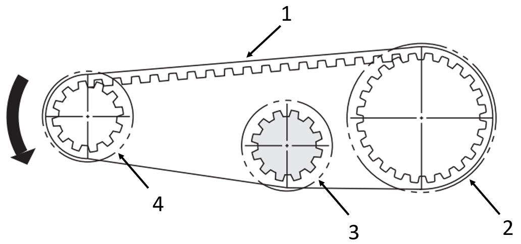
Application example: of toothed belt drives
(1) Toothed belt, (2) driven Timing pulleys with crimp disc, (3) idler pulley with crimp disc, (4) driving Timing pulleys with crimp disc
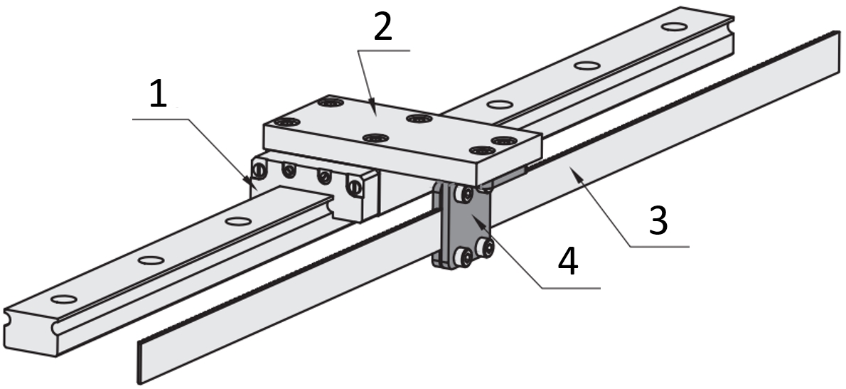
Application example: Timing belt
(1) Linear guide, (2) mounting plate, (3) Timing belt, (4) Screw-on terminal
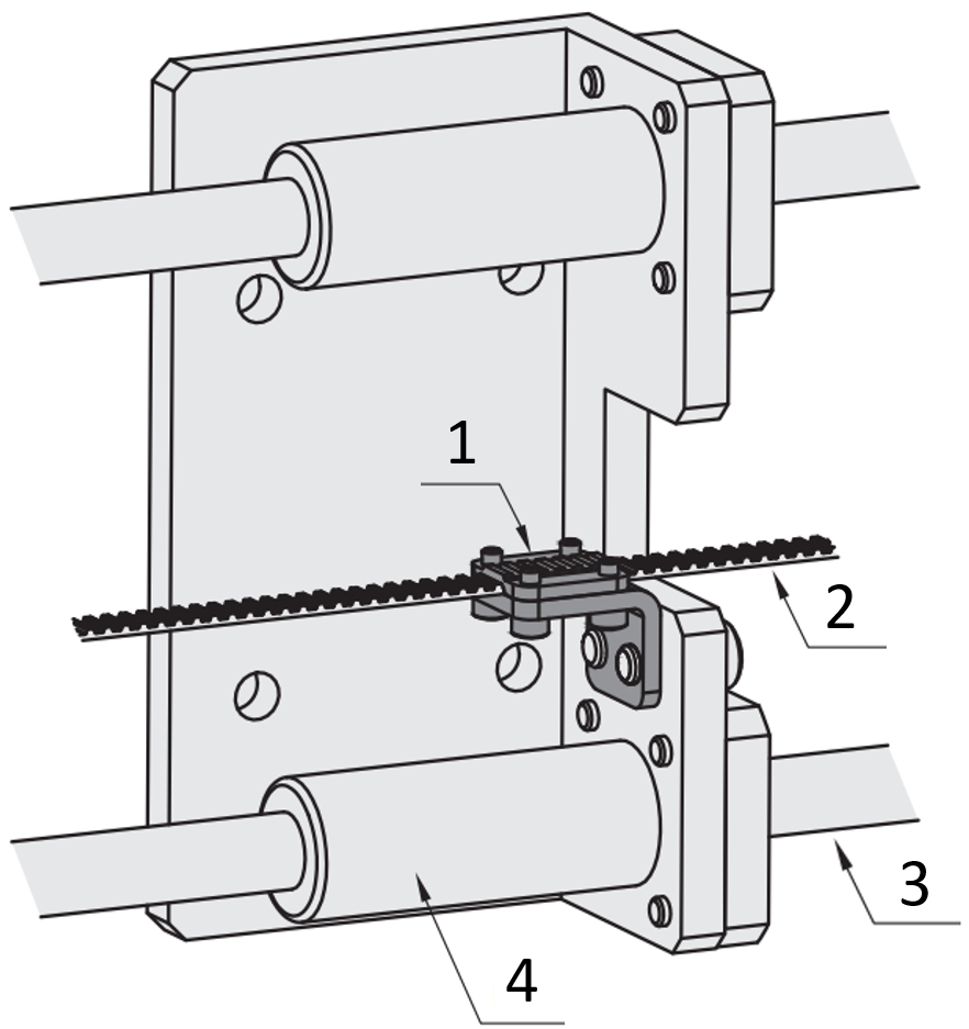
Application example: Timing belt
(1) Bolt-on terminal, (2) Timing belt, (3) Linear shaft, (4) Linear bushings
Industrial Applications


Basic information
| Belt shape | Belt Clamp Plates |
|---|
Configure
Basic Attributes
-
Belt Width (mm)(mm)
-
Belt Width (Inch)(Inch)
-
A(mm)
-
B(mm)
-
C(mm)
-
L(mm)
-
S(mm)
-
Z
-
Type
- TBLG
-
Belt Type
- XL
- L
- T5
- S3M
- S5M
- S8M
-
Filter by CAD data type
- 2D
- 3D
Filter by standard shipping days
-
- All
- 9 Days or Less
Optional Attributes
- The specifications and dimensions of some parts may not be fully covered. For exact details, refer to manufacturer catalogs .
Frequently Asked Questions (FAQ)
-
Question:
Where does the idler pulleys have to be placed on the timing belt?
-
Answer:
As a rule, the idler pulleys are positioned on the slack side, since the tension of the timing belt is here lowest during operation. Ideally, the timing belt is tensioned from the inside, because this prevents the timing belt from bending alternately. This is particularly recommended for timing belts with a steel tension cord. The idler pulley should always be larger than the smallest timing pulley of the belt drive system.
-
Question:
For what purpose can a timing belt with a round profile be used for?
-
Answer:
Round profile timing belts can be used in many applications. These are well suited for transmitting torque. In addition, the reverse play is very low due to the round profile shape with changing direction of rotation. The timing belts are also well suited for highly precise positioning. Timing belts with a round tooth profile can therefore often be found in 3D printers.
-
Question:
Can multiple belts be used for the transfer?
-
Answer:
A transmission can take place via one or more timing belts. If an equal distribution of the forces across the individual belts is not possible, it must be ensured that one belt alone can withstand the maximum load. In order to enable uniform distribution of forces, a precise adjustment is necessary. For this purpose, a toothed belt disc with clamping sleeve can be used, because it can be adjusted continuously and ensure uniform distribution.
-
Question:
Can a timing belt used for transmission?
-
Answer:
With timing belts, a gear ratio or reduction in a drive is possible. The gear ratio is established based on the number of teeth on the pulleys. It should be ensured that the minimum number of teeth of the timing pulley disc is not undercut.
-
Question:
What is the possible tensile stress for timing belts?
-
Answer:
The maximum allowable tension for MISUMI timing belts depends on the belt type, speed of rotation and belt pulley diameter. For more information, click on this link.
-
Question:
What is the minimum size of timing pulleys?
-
Answer:
The minimum size or the minimum number of teeth of a timing pulley depends on the belt type used and the height of the applied speed or rotation. You can find more detailed information about the minimum number of teeth of timing pulley discs in the selection of Timing Pulleys available as a PDF.
-
Question:
Does a timing belt stretch a lot?
-
Answer:
As opposed to a roller chain, the expansion is small. The length extension of timing belts is very stable. Therefore, it is not absolutely necessary to re-tension the timing belt during operation, as is necessary for chain drives. This makes the timing belt very easy to maintain compared to the chain. However, it should be ensured that the timing belt is free of oil, as the natural rubber could swell.
-
Question:
What is the purpose of a timing belt?
-
Answer:
The primary task of a timing belt is the synchronous and slip-free transmission of force or power. Depending on the task, various profile shapes are available for timing belts. These can be roughly divided into drive, conveying and positioning. In the following overview, you can view the various areas of use: Overview as PDF
MISUMI Unit еxample related to this product
Tech Support
- Technical Support
- Tel:+49 69 668173-0 / FAX:+49 69 668173-360
- Technical Inquiry
Payment Method


On-Demand Manufacturing
Certificates


Copyright © MISUMI Corporation All Rights Reserved.