Ball screws / compact flange / diameter 25 / pitch 5 / C10
Part Number
Once your search is narrowed to one product,
the corresponding part number is displayed here.
- Drawing / Specifications
- 3D Preview 3D preview is available after complete configuration
- Part Numbers
- More Information
- Catalog
- Technical Information
Dimensional Drawing

View X-X
| P | Tolerance |
| 10 | 0 -0.009 |
| 11 to 15 | 0 -0.011 |
* Collar included (1 pc.) "M" Material: EN 1.1191 Equiv. "S" Surface Treatment: Black Oxide
| Nut Type | Type | Accuracy Grade | Shaft Dia. | Lead | Screw Shaft | Nut | |||||
| Standard | F, P Configurable | [M] Material | [H] Hardness | [S] Surface Treatment | [M] Material | [H] Hardness | [S] Surface Treatment | ||||
| Compact Nut | BSSC | BSSCK | C10 | 25 | 5 | EN 1.1203 Equiv. | Induction hardened 56 to 62HRC | — | EN 1.7258 Equiv. | Carburized 58 to 62HRC | — |
Specification Table
| Part Number | — | L | — | F | — | P |
| BSSC2505 BSSCK2505 | — | 521 | ||||
| — | 300 | — | F32 | — | P13 |
| Nut Type | Accuracy Grade | Part Number | 1 mm Increments | Y | Ball Dia. | Ball Center Dia. | Screw Root Dia. | Number of Circuits | Basic Load Rating | Axial Play Clearance | Twisting Direction | |||||
| Type | Screw Shaft O.D. | Lead | L | * F | * P | C (Dynamic) kN | Co (Static) kN | |||||||||
| Compact Nut | C10 | BSSC | 25 | 05 | 200 to 2000 | 27 | 15 | L-118 | 3.175 | 25.5 | (22.25) | 3 turns, 1 row | 5.47 | 12.52 | 0.10 or Less | Right |
| BSSCK | 27 to 45 | 10 to 15 | L- (91+F) | |||||||||||||
| * F and P are configurable for BSSCK only. [!] F ≤ P × 3. [!] Y (Nut Motion Range) > (Nut Overall Length). kgf = N × 0.101972 | ||||||||||||||||
Alterations
| Part Number | — | L | — | F | — | P | — | (FC·KC, etc.) |
| BSSC2505 | — | 350 | — | KC10 |
| Alterations | Code | Spec. | Alterations | Code | Spec. | ||||||||||||||||
No Machining on Both Shaft Ends [ ! ]A nut is mounted to the temporary shaft before the product is shipped. | WNC | Does not machine any of the both shaft ends. Ordering Code WNC-S20-F80 [ ! ] Annealing may lower hardness on the annealed area + 25 mm fore and aft. [ ! ]S+F ≤ L/2 [ ! ]L- (S+F) ≤ Y+50 [ ! ] On the annealed area + 25 mm fore and aft, axis run-out may be larger than indicated by the Catalog standard. | Wrench Flats on Fixed Side | SZC | Adds wrench flats on the fixed side shaft end. Ordering Code SZC [ ! ] Ball bearings will fall out, if the ball nut crosses the wrench flats. | ||||||||||||||||
No Machining on Support Side Shaft End | NC | No machining added on the support side shaft end. Ordering Code NC | Keyway on Fixed Side Shaft End | KC | Adds a keyway on the fixed side shaft end. KC = 1 mm Increments Ordering Code KC15 [ ! ]5 ≤ KC ≤ P × 3 KC ≤ F-1 | ||||||||||||||||
Ball Nut Orientation Reversed
| RLC | Changes the nut direction. Ordering Code RLC | Keyway on Fixed Side Shaft End | KLC | The position of keyway on fixed side shaft end can be specified. (Keyway dimensions are the same as KC.) K, S = 1 mm Increments Ordering Code KLC-K7-S2 [ ! ]6 ≤ K+S ≤ P × 3 K+S ≤ F-2 | ||||||||||||||||
No Retaining Ring Groove on Support Side Shaft End | RNC | No Retaining Ring Groove on Support Side Shaft End. Ordering Code RNC [ NG ] Combination with FC is not available. | Flat Machined on Fixed Side Shaft End | SC | Adds a flat on the fixed side shaft end. SC = 1 mm Increments Ordering Code SC7 [ ! ]5 ≤ SC ≤ P × 3 SC ≤ F-1 | ||||||||||||||||
Change Support Side Shaft End Machining | GC | Changes the machining on the support side. Q is selectable from 10, 12, 15 or 20 G = 1 mm Increments Ordering Code GC-Q10-G20 [ ! ] 5 ≤ G ≤ Q × 3 [ ! ] Y dimension is shortened. [ ! ] No Retaining Ring Groove [ NG ] Combination with FC is not available | Flat Machined on Fixed Side Shaft End (2 Locations) JIS−SWC SGC  | JIS−SWC SGC | Adds two flats on the fixed side shaft end. JIS−SWC: 90° Position SGC: 120° Position 1 mm Increments Ordering Code JIS−SWC10 [ ! ]5 ≤ JIS−SWC·SGC ≤ P × 3 JIS−SWC·SGC ≤ F-1 | ||||||||||||||||
Change Support Side Shaft End Length | FC | Changes the length of the support side shaft end. FC = 1 mm Increments Ordering Code FC20 [ ! ]19 ≤ FC ≤ 60 [ ! ] Y dimension is shortened. [NG] Combination with GC is not available | Installing Special Temporary Shaft | TAS | Dedicated Temporary Shafts suitable for Ball Screws are installed. When removing Nut from Screw Shaft, always use Special Temporary Shaft. | ||||||||||||||||
Tapped Hole on Support Side Shaft End | MC | Adds a tapped hole on the support side shaft end. MC = 1 mm Increments Ordering Code MC25
| |||||||||||||||||||


[!]Specify an alteration position to be 2 mm or more away from the stepped part. (Refer to the diagram in Caution (1))
[!] When adding multiple alterations, there must be 2 mm or more clearance between each machined part. (Refer to the diagram in Caution (2))
[!]When flat machining, wrench flats, square chamfering and keyway alterations are combined with each other, their orientations will be random. (Refer to the diagram in Caution (3))
[!] Do not specify multiple alterations in such a way that they overlap with each other in the rotating direction on the same shaft. (Refer to the diagram in Caution (4))
[ ! ] When two or more alterations are specified on a shaft, they may not be machined due to correlation.
| Caution (1) Specify the alteration portion to be 2 mm or more away from the stepped part .  | Caution (2) 2 mm or more is required for the clearance between multiple alterations .  | Caution (3) When the multiple alterations are combined with each other, their orientations are random and thus, are not always aligned in a linear arrangement. (One example of this is shown in the diagram below.)  For Alterations A and B added to the same shaft, as shown in the diagram above, their orientations are random and thus, there are some cases where they are not aligned in a linear arrangement. | Caution (4) Do not specify multiple alterations in such a way that they overlap with each other on the same shaft. (Any diagram as shown below is not acceptable.) 
|
Part Number:
- In order to open the 3D preview, the part number must be fixed.
3D preview is not available, because the part number has not yet been determined.
Part Number
|
|---|
| BSSC2505-[200-2000/1] |
| BSSCK2505-[200-2000/1]-F[27-45/1]-P[10-15/1] |
| Part Number | Minimum order quantity | Volume Discount | Circuit System | Shaft Overall Length L (mm) | Shaft End Length F (mm) | Shaft Dia. P (Ø) | Shaft End Dimension (Fixed, Configurable) | Shaft Dia. P (φ) | |
|---|---|---|---|---|---|---|---|---|---|
| 1 | 20 Days | End Deflector Type | 200 ~ 2000 | 27 | 15 | Stationary | - | ||
| 1 | 20 Days | Tube Type | 200 ~ 2000 | 27 ~ 45 | - | Configuration | 10 ~ 15 |
Loading...
Specifications/Overview
·Compact O.D. · Lower profile sliders can be used. · Longer strokes

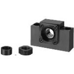
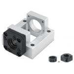
| ■Peripherals: Combination with the following parts is available. | ||||
 |  |  |  | |
| Support Units (Square, Low Profile Type) | Support Units (Round Type) | Nut Bracket (Block Type) | ||
| ■Combination with Support Units | ■Combination with Nut Brackets | ||||||||||||
| Ball Screw Part Number | Recommended Support Unit | Ball Screw Part Number | Recommended Nut Bracket | ||||||||||
| Type | Screw Shaft O.D. | Lead | Part Number | Shape | Fixed Side | Support Side | Type | Screw Shaft O.D. | Lead | Part Number | |||
| Type | No. | Type | No. | ||||||||||
| BSSC | 25 | 05 | BSV | 20 | Square Low Profile | ○ | BSSC | 25 | 05 | BNFB BNFM BNFR BNFA | 2005C | ||
| BUV | 20 | ○ | 2010C | ||||||||||
| BRW | 20 | Round | ○ | 2505C | |||||||||
| BUR | 20 | ○ | [!] Other than the part numbers shown above, a variety of Nut Brackets are also available. | ||||||||||
| [!] Other than the part numbers shown above, a rich variety of Support Units are also available. | |||||||||||||
| Height 2 mm Lower Profile |
| ■Lower profile linear units can be designed by using in combination with Support Units Low Profile Type. |
 |
| [Low Profile Type][Standard Type] |
General Information - Ball Screws

Ball Screw Selection Details
- Material: steel
- Coatings: uncoated, LTBC coating, phosphate conversion coating
- Heat treatment: up to 62HRC
- Precision category: C3, C5, C7, C10
- Precision classes: precision class, standard class
- Slope: 1 to 32 mm
- Outer diameter: 6 to 32 mm
- Length (mm): 100 to 2000
- Nut shape: round flange, square flange, compact flange, block shape
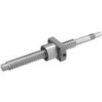
Description/Basics
Ball screws are intended for converting rotary motion to linear motion. This can also be done in reverse order from linear to rotary motion. With the ball screws, this is achieved extremely precisely due to their low play. In mechanical engineering, the ball thread drive is an indispensable feature and is indispensable in precision applications. These work in horizontal and vertical orientation, allowing to shift, raise and lower devices.
The ball screws are often driven by motors and shaft couplings, or manually via rotary/crank handles.
When utilising a keyway, it is recommended using a machine key, as these can be combined excellently due to the manufacturing tolerances.
For a smooth process, it is recommended installing the ball screw with a fixed bearing and a floating bearing. This ensures that the ball screw does not bend due to compression and generate vibrations. For this purpose, MISUMI offers the right support units drives in various designs. For more information on how to install ball screws, see the Installation Instructions available as a PDF.
Ball screw nuts are available in different shapes. These enable versatile utilisation, even in confined spaces. Due to their high precision, the ball screws can also provide a high level of repeatability that is necessary in precise positioning applications. These can be utilised, for example, for measuring devices or in 3D printing. It is recommended to use a pre-stressed ball screw for highly precise applications. Due to the pre-tensioning, the axial play is almost zero unlike a conventional ball screw. In addition, MISUMI offers single axis actuators (locating units) for such applications, which as drives are already equipped with precise ball screws.
In smaller applications, a slide screw or a so-called miniature screw drive can be used. Due to their design, these are very compact, but suitable for lower axial loads.
If very high forces occur, a lead screw could also be considered.
Which ball screw is the right one for your application must be calculated based on the existing factors and influences. You can use the selection Ball Screws that is available as a PDF for this purpose. You can also find the service life calculation in this link.
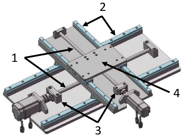
Application Examples - Ball Screws
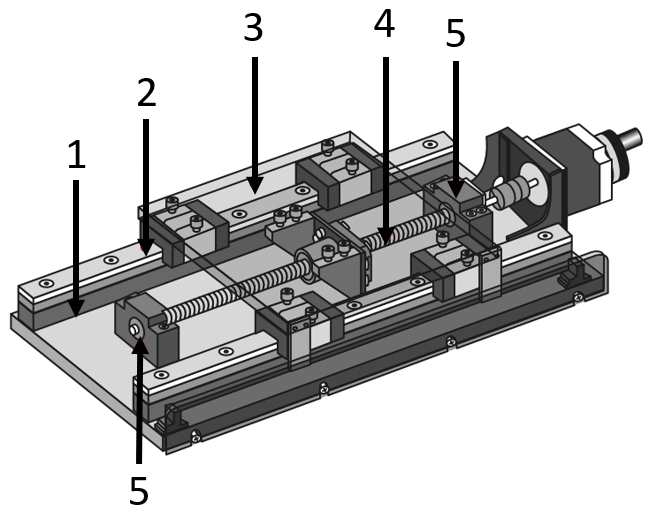
Application example for positioning stages
(1) Linear guide accessories, (2) Standard linear guide, (3) Table plate (meviy), (4) Ball screw, (5) Support units
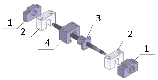
Application example for the ball screw
(1)) Support units, (2) Ball screw nut stops, (3) Ball screw, (4) Ball screw nut mountings
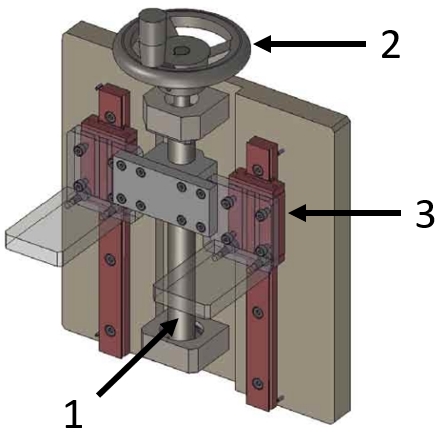
Application example for a lifting device
(1) Ball screw, (2) Standard linear guide, (3) Support units, (4) Table top (meviy)
(1) Ball screw, (2) Standard linear guide, (3) Support units, (4) Table top (meviy)
Industrial Applications


Basic information
| Type | Rolled | Nut Type | Standard Nuts | Accuracy Grade | C10 |
|---|---|---|---|---|---|
| Screw Shaft O.D.(mm) | 25 | Lead(mm) | 5 | Preload | Not Preloaded |
| Conditions of Use | Standard | Twisting Direction | Right | Axial Play | 0.10 or Less |
| Nut structure | 1-fach | Number of Circuits(Rows x Windings) | 1 x 3 | Basic Load Rating Dynamic Rating(N) | 5470 |
| Basic Load Rating Static Rating(N) | 12520 | Grease Type | Standard | Nut Size | Compact |
Configure
Basic Attributes
-
Shaft Overall Length L(mm)
-
Shaft End Length F(mm)
-
Shaft Dia. P(Ø)
-
Shaft End Dimension (Fixed, Configurable)
- Configuration
- Stationary
-
Shaft Dia. P(φ)
-
Type
- BSSC2505
- BSSCK2505
-
Filter by CAD data type
- 2D
- 3D
Filter by standard shipping days
-
- All
- 20 Days or Less
Optional Attributes
- The specifications and dimensions of some parts may not be fully covered. For exact details, refer to manufacturer catalogs .
Frequently Asked Questions (FAQ)
-
Question:
How do you mount a ball screw drive?
-
Answer:
A ball screw should be stored with a fixed bearing and a floating bearing. The fixed bearing should ideally be installed on the engine side or the drive side. Fixed bearing housings come already equipped with angular contact ball bearings to absorb axial forces. This combination makes ball screws an ideal candidate for positioning. However, a preloaded threaded drive should be selected for very high precision as it has very little axial play.
-
Question:
Why should a fixed and floating bearing be used?
-
Answer:
A fixed bearing housing is often used on the drive side. The floating bearing with housing, on the other hand, allows a small axial deviation and thus compensates for a change in length or a length tolerance. This prevents compression and bending of the ball screw and an imbalance through the length compensation. This may already occur by heating the spindle or application. Fixed and floating bearings are recommended in many rotary applications.
-
Question:
How does a ball screw work?
-
Answer:
A ball screw works similarly to a profile rail guide . In the nut of the ball screw, balls are in a closed ball circulation, which are guided to the spindle by the circular alignment. Thus, an unlimited stroke is theoretically possible, which, however, is limited by the length of the spindle. It is important to ensure that the nut of the ball screw is not removed from the spindle, because the balls can fall out as a result.
-
Question:
Why does the spindle oscillate in a ball screw drive?
-
Answer:
One possible cause for this could be that the ball screw is exposed to excessively high rotational speeds. The permissible rotational speed should not be higher than 80% of the critical speed. Here, attention should be paid not only to the visibly rotating components, but also to the rotational speed of the balls. Further information can be found in the ball screw driver selection as a PDF. Another possibility for the spindle to oscillate could be a compression of the spindle. Therefore, it is important to install a ball screw with a fixed bearing and a floating bearing so that these stresses can be compensated through a floating bearing. MISUMI offers this as ready-to-install bearing housings.
-
Question:
Is the ball screw nut removable?
-
Answer:
The ball screw nut or ball wrap nut should not be removed from the lead screw. There is a risk that the balls will fall out of the nut. This also means that the nut should not be extended over the threaded surface of the spindle. To remove the nut, you can work carefully with a transition shaft with the appropriate core diameter. However, MISUMI also offers an option [TAS] that provides a transition shaft with the ball screw drive. If a ball screw with reverse ball screw is required, the option [RLC] can be supplied with the ball screw nut installed in reverse.
-
Question:
Can you replace just the ball screw nut?
-
Answer:
A ball screw drive should always be replaced as one unit. If damage or wear has already occurred on the spindle, the accuracy of the ball screw drive can no longer be guaranteed. Therefore, it is always recommended replacing spindle and nut together. In addition, the ball screw nut should generally not be removed from the spindle. As a result, the balls that are necessary for the transmission of force may fall out.
-
Question:
How long does a ball screw lasts?
-
Answer:
How long a ball screw can withstand an application depends on many factors. Therefore, it is not possible to say generally how long a ball screw will last. When a ball screw should be replaced, it must be determined mathematically. In the following link, you will find the appropriate calculation formula for the lifetime available as a PDF.
-
Question:
How large is the axial play of a ball screw?
-
Answer:
The axial play varies depending on the precision class and size of the ball screw. You can find the appropriate axial play for different ball screws under the selection Ball Screws available as a PDF .
-
Question:
What must be considered when installing a ball screw?
-
Answer:
When installing a ball screw spindle, more must be taken into account than just ensuring that it is installed tension-free. There are a few things you should observe even before installation. You can view these as a PDF under Precautions.
-
Question:
Are the ball screws lubricated?
-
Answer:
The ball screws from MISUMI are pre-greased. Various lubricants are available for this purpose. Lithium-saponified lubricants are used as standard lubricants. In addition, MISUMI offers heat-resistant lubricants or lubricants suitable for cleanrooms. You can find further information under Installation and Maintenance available as a PDF.
Complementary Products
-
 Support Units / Square / Fixed Side / with Dowel holes
MISUMI Standard Price : 96.59 € Shipping Days: Same day


Tech Support
- Technical Support
- Tel:+49 69 668173-0 / FAX:+49 69 668173-360
- Technical Inquiry
Payment Method


On-Demand Manufacturing
Certificates


Copyright © MISUMI Corporation All Rights Reserved.