L-Shaped Sheet Metal Mounting Plate / Bracket -Custom Dimensions Type- FADBS
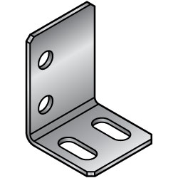
- Order quantities extended (D-JIT)
Part Number
Once your search is narrowed to one product,
the corresponding part number is displayed here.
- Drawing / Specifications
- 3D Preview 3D preview is available after complete configuration
- Part Numbers
- Catalog
- Technical Information
Dimensional Drawing
 | (Common Dimension)  |
[ ! ] For details on specifications and machining limits, see here
[ ! ] K Dimension: K ≤ NAx5
■Hole Type Selection Chart
| Hole Type | Bolt Hole | Tapped Hole (Coarse) | ||
| Code | N・NA | M | ||
| Shape Diagram |
|  |

| Part Number | [ M ] Material | [ S ] Surface Treatment | ||
| Type | Material Symbol | |||
| FADBS | SP | T0.8 to 3.2 T4.5 to 6.0 T9.0 | : EN 1.0330 Equiv. : EN 1.0320 Equiv. (hot coiled) : EN 1.0038 Equiv. (Black) | - |
| SPB | Black Oxide | |||
| SPU | Trivalent Chromate (Clear) | |||
| SPK | Trivalent Chromate (Black) | |||
| AM | EN AW-5052 Equiv. | — | ||
| AMW | Anodize (Clear) | |||
| AMB | Anodize (Black) | |||
| SUD | T0.8 to 6.0 T9.0 | : EN 1.4301 Equiv. (Passivated 2B) : EN 1.4301 Equiv. (No.1) | - | |
Specification Table
| Part Number | - | T | - | A | - | B | - | L | - | X | - | H | - | G | - | Hole Specification① Code / Nominal Dia. | - | Y | - | V | - | S | - | Hole Specification② Code / Nominal Dia. | - | K | ||
| Type | - | Material Symbol | ||||||||||||||||||||||||||
| FADBS | - | SP | - | T2.3 | - | A30 | - | B20 | - | L20 | - | X15 | - | H15 | - | G10 | - | N3 | - | Y6 | - | V8 | - | S10 | - | NA3 | - | K5 |
| Part Number | Selection | 1 mm Increments | X | H | G | Hole Specification① | Y | V | S | Hole Specification② | K | ||||
| Type | Material Symbol | T | A | B | L | Code / Specify Method | Code / Specify Method | ||||||||
| FADBS | SP SPB SPU SPK | 0.8 ・ 1.0 ・ 1.2 ・ 1.6 ・ 2.3 3.2 ・ 4.5 ・ 6.0 ・ 9.0 | 20 to 200 (300) [ ! ] | 15 to 200 [ ! ] | 10 to 200 [ ! ] | 0.1 mm Increments | N (Bolt Hole) 0・3・4・5 6・8・10 (Select) [ ! ] | M (Tapped Hole) 0・3・4・5 6・8・10 (Select) [ ! ] | 0.1 mm Increments | NA (Bolt Hole) 0・3・4・5 6・8・10 (Select) [ ! ] | 0.1 mm Increments [ ! ]K≤NA×5 | ||||
| AM AMW AMB | 1.0 ・ 1.5 ・ 2.0 ・ 3.0 ・ 4.0 ・ 5.0 | ||||||||||||||
| SUD | 0.8 ・ 1.0 ・ 1.2 ・ 1.5 ・ 2.0 3.0 ・ 4.0 ・ 5.0 ・ 6.0 ・ 9.0 | ||||||||||||||
| [ ! ] For T6.0, A≤300,B≥20, L≥20 [ ! ] For T9.0, A≤300,B≥32, L≥20 [ ! ] Holes may deform if the hole locations are too close to the ends and bends, but they will be machined as specified if they are within the machining limits. | |||||||||||||||
| N・NA Specified Value | Through Hole Dia.(d) |
| 0 | (No Hole) |
| 3 | 3.5 |
| 4 | 4.5 |
| 5 | 5.5 |
| 6 | 6.5 |
| 8 | 9 |
| 10 | 11 |
| T | N・NA (Bolt Hole) | M (Tapped Hole) |
| 0.8 | 0・3・4・5・6・8・10 | 0 |
| 1.0、1.2 | 0・3 | |
| 1.5、1.6 | 0・3・4 | |
| 2.0、2.3 | 0・3・4・5・6 | |
| 3.0、3.2 | 0・3・4・5・6・8 | |
| 4.0 to 6.0 | 0・3・4・5・6・8・10 | |
| 9.0 | 0・5・6・8・10 | 0・5・6・8・10 |
Alteration
| Alterations | Slotted Hole Angle Change |
 | |
| Code | RC |
| Spec. | Slotted holes are changed as shown above. [!] Note the dimensional relationship Specifying Method Add RC to the end of a Part Number. (Example) ... -RC |
Specifications, Machining Limits
[Standard Machined Dimension Tolerances]
| Product | Dimension Range (A, B dimension) | 6 or less | Over 6, and 30 or less | Over 30, and 120 or less | Over 120, and 400 or less |
| Sheet Metal (Bent Products) | Tolerance(a・b) | ±0.3 | ±0.5 | ±0.8 | ±1.2 |
for parts formed by press working from sheet metal is used.
[ ! ] 2. Burr height 0.1 or less
[ ! ] 3. Bend angle tolerance ±1°

[ ! ] 4. In case of the thin plates, the tap ridges may be crushed, so please be careful when tightening.
[ ! ] 5. When changing to a specification without holes, anodizing with T4.0 or more may cause a hang hole to be formed as shown in the figure below.

[ ! ] 6. Slotted holes may be shaped as shown below depending on dimensions.
(The function as a mounting hole is not affected.)
[ ! ] 7. There are machining limits for sections b, f, g below.
| T | f (Distance between the hole and the bend) | b (Distance between the hole and the end face) | g | ||||||
| EN 1.0330 Equiv. EN 1.0320 Equiv. (hot coiled) EN 1.0038 Equiv. | EN AW-5052 Equiv. | EN 1.4301 Equiv. | Through Hole | Tapped Hole | Slotted Hole parallel to Hole Bending with Tolerance | ||||
| L Bend | Z, Convex Bend | L Bend | Z, Convex Bend | ||||||
| 0.8 | ー | 0.8 | 2 | 3 | ー | ー | 3.5 | 1 | 5 |
| 1.0 | 1.0 | 1.0 | 2 | 3 | 3 | 5.5 | 3.5 | 1 | 5.5 |
| 1.2 | ー | 1.2 | 2 | 3 | 3 | 5.5 | 3.5 | 1 | 5.5 |
| 1.6 | 1.5 | 1.5 | 2 | 3.5 | 3 | 6 | 4 | 1 | 6 |
| 2.3 | 2.0 | 2.0 | 2 | 4.5 | 3 | 7 | 5 | 1.5 | 7 |
| 3.2 | 3.0 | 3.0 | 2 | 6.5 | 3 | 9 | 7 | 1.5 | 9 |
| 4.5 | 4.0 | 4.0 | 3 | 7.5 | 4 | 11 | 8(9) | 2 | 11 |
| ー | 5.0 | 5.0 | 3 | 14 | 4 | 16 | 15 | 2.5 | 18 |
| 6.0 | ー | 6.0 | 3 | 14 | 4 | 16 | 15 | 2.5 | 18 |
| 9.0 | ー | 9.0 | 20 | ー | 20.5 | ー | 20 | 4 | 20 |

[ ! ] Slotted hole f parallel to T4.0 and T4.5 will be (9).
[ ! ] The hole may be deformed if specified at the limit value shown above.
[ ! ] 8. There will be some scratches left by press brake. Use r, e, d dimension for reference only.
| T | R after Bending | Brake Scratches | |||
| Position | Depth | ||||
| EN 1.0330 Equiv. EN 1.0320 Equiv. (hot coiled) EN 1.0038 Equiv. | EN AW-5052 Equiv. | EN 1.4301 Equiv. | (r) | (e) | (d) |
| 0.8 | ー | 0.8 | 0.8 | 5 | 0.1 |
| 1.0 | 1.0 | 1.0 | 1 | 5 | 0.1 |
| 1.2 | ー | 1.2 | 1.2 | 5 | 0.1 |
| 1.6 | 1.5 | 1.5 | 1.5 | 6 | 0.1 |
| 2.3 | 2.0 | 2.0 | 2.0 | 7.5 | 0.1 |
| 3.2 | 3.0 | 3.0 | 3.0 | 10.5 | 0.2 |
| 4.5 | 4.0 | 4.0 | 4.0 | 13.5 | 0.3 |
| ー | 5.0 | 5.0 | 5.0 | 17 | 0.5 |
| 6.0 | ー | 6.0 | 6.0 | 17 | 0.5 |
| 9.0 | ー | 9.0 | 9.0 | 27 | 0.8 |

[ ! ] If the bend and hole are close to each other, r may be smaller.
[ ! ] 9. Bending causes biting and bulging.

[ ! ] 10. Since it is manufactured with minimum bending R, there is a possibility of breakage if it is used in an environment where stress is concentrated, such as impact.
| None | Black Oxide | Trivalent Chromate (White) | Trivalent Chromate (Black) | |
| SP | SPB | SPU | SPK | |
| EN 1.0330 Equiv. T0.8 to 3.2 |  |  |  |  |
| EN 1.0320 Equiv. (hot coiled) T4.5 to 6.0 |  |  |  |  |
| EN 1.0038 Equiv. (Black) T9.0 |  |  |  |  |
| None | Anodize (Clear) | Anodize (Black) | |
| AM | AMW | AMB | |
| EN AW-5052 Equiv. |  |  |  |
| None | |
| SUD | |
| EN 1.4301 Equiv. (2B) T0.8 to 6.0 |  |
| EN 1.4301 Equiv.(No.1) T9.0 |  |
App. Example

Part Number:
- In order to open the 3D preview, the part number must be fixed.
3D preview is not available, because the part number has not yet been determined.
| Part Number | Minimum order quantity | Volume Discount | RoHS | Material | Surface Treatment | A (mm) | B (mm) | L (mm) | T (mm) | |
|---|---|---|---|---|---|---|---|---|---|---|
| 1 | 7 Days | 10 | EN AW-5052 Equiv. | Not Provided | 20 ~ 200 | 15 ~ 200 | 10 ~ 200 | 1.5 ~ 5 | ||
| 1 | 9 Days | 10 | EN AW-5052 Equiv. | Black Anodize | 20 ~ 200 | 15 ~ 200 | 10 ~ 200 | 1.5 ~ 5 | ||
| 1 | 9 Days | 10 | EN AW-5052 Equiv. | Clear Anodize | 20 ~ 200 | 15 ~ 200 | 10 ~ 200 | 1.5 ~ 5 | ||
| 1 | 7 Days | 10 | EN 1.0330 Equiv. (EN 1.0320 Equiv. (hot-rolled)) | Not Provided | 20 ~ 300 | 15 ~ 200 | 10 ~ 200 | 1.6 ~ 6 | ||
| 1 | 9 Days | 10 | EN 1.0330 Equiv. (EN 1.0320 Equiv. (hot-rolled)) | Black Oxide | 20 ~ 300 | 15 ~ 200 | 10 ~ 200 | 1.6 ~ 6 | ||
| 1 | 7 Days | 10 | EN 1.0330 Equiv. (EN 1.0320 Equiv. (hot-rolled)) | Trivalent Chromate (Black) | 20 ~ 300 | 15 ~ 200 | 10 ~ 200 | 1.6 ~ 6 | ||
| 1 | 7 Days | 10 | EN 1.0330 Equiv. (EN 1.0320 Equiv. (hot-rolled)) | Trivalent Chromate (White) | 20 ~ 300 | 15 ~ 200 | 10 ~ 200 | 1.6 ~ 6 | ||
| 1 | 7 Days | 10 | EN 1.4301 Equiv. (2B) | Not Provided | 20 ~ 200 | 15 ~ 200 | 10 ~ 200 | 1 ~ 5 |
Loading...
Basic information
| Type | Sheet Metal | Part Mounting Hole | N/A | Slotted Hole | Yes |
|---|---|---|---|---|---|
| Hole Position | Free Dimension | Number of Front Holes | 2 | Number of Bottom Holes | 2 |
| Type | FADBS | Type | Dimension Configurable Type |
Configure
Basic Attributes
-
Material
- EN AW-5052 Equiv.
- EN 1.0330 Equiv. (EN 1.0320 Equiv. (hot-rolled))
- EN 1.4301 Equiv. (2B)
-
Surface Treatment
- Black Anodize
- Black Oxide
- Clear Anodize
- Not Provided
- Trivalent Chromate (Black)
- Trivalent Chromate (White)
-
A(mm)
-
B(mm)
-
L(mm)
-
T(mm)
-
Type
- FADBS-AM
- FADBS-AMB
- FADBS-AMW
- FADBS-SP
- FADBS-SPB
- FADBS-SPK
- FADBS-SPU
- FADBS-SUD
-
Filter by CAD data type
- 2D
- 3D
Filter by standard shipping days
-
- All
- 7 Days or Less
- 9 Days or Less
Optional Attributes
- The specifications and dimensions of some parts may not be fully covered. For exact details, refer to manufacturer catalogs .
Tech Support
- Technical Support
- Tel:+49 69 668173-0 / FAX:+49 69 668173-360
- Technical Inquiry
Payment Method


On-Demand Manufacturing
Certificates


Copyright © MISUMI Corporation All Rights Reserved.