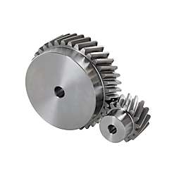
Helical Gears - Module 2.0, Shaft Bore Configurable Type
Click on this image to zoom in.
Click on this image to zoom in.
Right-twisted helical gears engage with left-twisted helical gears.
Four types of shaft bore are selectable: straight bore, straight bore + tap, keyway, and keyway + tap.
Available alterations: Set screw alteration, tapped hole dimension change, stepped hole, both ends stepped hole, hub cut, hub diameter cut, side slotted hole, side through hole, side tapped hole, and side counterbored hole alterations are possible.
Lineup by moduleModule 1.0Module 1.5Module 2.5Module 3.0
(i)Remark
- The tooth shape in the 3D drawing is not generated with CAD data download. Refer to the reference circle on the 3D drawing for more information.
Part Number
Once your search is narrowed to one product,
the corresponding part number is displayed here.
- Drawing / Specifications
- 3D Preview 3D preview is available after complete configuration
- Part Numbers
- More Information
Shape A | Shape B |
[!] Relative positioning of keyway and teeth is not fixed. | ||||||||||||


| Gear dimensions | ||||
| Datum Section of Gears | Teeth perpendicular | |||
| Module | 2.0 | |||
| Pressure Angle | 20° | |||
| Helix Angle | 19° 31′42″ | |||
| Gear Accuracy | JIS B 1702-1, ISO 1328-1, Flank Tolerance Class 8 | |||
| Type | [M] Material | [S] Surface Treatment | [A]Accessory | ||
| Straight Bore | Straight Bore + Tap | Keyway, Keyway + Tap | |||
| HGEARHB | HGEARB | HGEARKB | EN 1.1191 Equiv. | — | Set Screw (EN 1.7220 Equiv. Black Oxide) |
| HGEARHBB | HGEARBB | HGEARKBB | Black Oxide | ||
| HGEARHBG | HGEARBG | HGEARKBG | Electroless Nickel Plating | ||
Specification Table
| Part Number | — | Number of Teeth | — | B | — | Gear Shape | — | P | — | Twisting Direction |
| HGEARHB2.0 | — | 25 | — | 20 | — | A | — | 10 | — | LH |
| HGEARBG2.0 | — | 38 | — | 20 | — | B | — | 20 | — | RH |
| HGEARKB2.0 | — | 18 | — | 20 | — | A | — | 12 | — | LH |
| Part Number | Number of Teeth | B Tooth Width | Gear Shape | Shaft Bore Dia. PH7 (1 mm Increments) | Twisting Direction | d Reference Circle Dia. | D Addendum Circle Dia. | G Dedendum Circle Dia. | H | L | ℓ1 | ℓ2 | M (Coarse) | *1 Allowable Torque (N⋅m) | |||
| Type | Module | Straight Bore Straight Bore + Tap | Keyway Keyway + Tap | Bending Strength | Tooth Surface Strength | ||||||||||||
| Straight Bore (Shape A, Shape B) HGEARHB HGEARHBB HGEARHBG Straight Bore + Tap (Shape B) HGEARB HGEARBB HGEARBG Keyway (Shape A) Keyway + Tap (Shape B) HGEARKB HGEARKBB HGEARKBG | 2.0 | 15 | 20 | A B | 8 to 15 | 8 to 12 | LH (Left) RH (Right) | 31.83 | 35.83 | 26.83 | 22 | 34 | 14 | 7 | M4 | 35.95 | 2.47 |
| 16 | 8 to 16 | 33.95 | 37.95 | 28.95 | 24 | 39.72 | 2.88 | ||||||||||
| 17 | 8 to 19 | 8 to 14 | 36.08 | 40.08 | 31.08 | 27 | 43.56 | 3.32 | |||||||||
| 18 | 8 to 21 | 8 to 16 | 38.20 | 42.20 | 33.20 | 29 | 47.46 | 3.80 | |||||||||
| 19 | 8 to 17 | 40.32 | 44.32 | 35.32 | 31 | 51.41 | 4.54 | ||||||||||
| 20 | 8 to 23 | 8 to 18 | 42.44 | 46.44 | 37.44 | 33 | 55.42 | 5.13 | |||||||||
| 21 | 8 to 19 | 44.56 | 48.56 | 39.56 | 35 | 59.47 | 5.76 | ||||||||||
| 22 | 8 to 25 | 8 to 21 | 46.69 | 50.69 | 41.69 | 37 | 63.57 | 6.43 | |||||||||
| 23 | 8 to 22 | 48.81 | 52.81 | 43.81 | 39 | 67.70 | 7.14 | ||||||||||
| 24 | 8 to 28 | 8 to 23 | 50.93 | 54.93 | 45.93 | 41 | 71.87 | 7.90 | |||||||||
| 25 | 53.05 | 57.05 | 48.05 | 44 | 76.07 | 8.70 | |||||||||||
| 26 | 8 to 30 | 8 to 27 | 55.17 | 59.17 | 50.17 | 46 | 80.30 | 9.54 | |||||||||
| 27 | 8 to 33 | 8 to 30 | 57.30 | 61.30 | 52.30 | 48 | 84.56 | 10.44 | |||||||||
| 28 | 59.42 | 63.42 | 54.42 | 50 | 88.84 | 11.37 | |||||||||||
| 29 | 8 to 35 | 8 to 31 | 61.54 | 65.54 | 56.54 | 52 | 93.15 | 12.36 | |||||||||
| 30 | 8 to 36 | 8 to 32 | 63.66 | 67.66 | 58.66 | 54 | 97.48 | 13.39 | |||||||||
| 32 | 8 to 38 | 8 to 33 | 67.91 | 71.91 | 62.91 | 58 | 106.19 | 15.60 | |||||||||
| 33 | 70.03 | 74.03 | 65.03 | 61 | 110.58 | 16.78 | |||||||||||
| 34 | 10 to 38 | 10 to 33 | 72.15 | 76.15 | 67.15 | 63 | M5 | 114.98 | 18.01 | ||||||||
| 35 | 10 to 40 | 10 to 35 | 74.27 | 78.27 | 69.27 | 65 | 119.39 | 19.28 | |||||||||
| 36 | 10 to 43 | 10 to 37 | 76.39 | 80.39 | 71.39 | 67 | 123.83 | 20.61 | |||||||||
| 38 | 80.64 | 84.64 | 75.64 | 70 | 132.73 | 23.42 | |||||||||||
| 39 | 82.76 | 86.76 | 77.76 | 137.20 | 24.91 | ||||||||||||
| 40 | 10 to 48 | 10 to 40 | 84.88 | 88.88 | 79.88 | 141.68 | 26.44 | ||||||||||
| 42 | 89.13 | 93.13 | 84.13 | 150.67 | 29.67 | ||||||||||||
| 44 | 93.37 | 97.37 | 88.37 | 159.70 | 33.12 | ||||||||||||
| 45 | 95.49 | 99.49 | 90.49 | 164.23 | 34.92 | ||||||||||||
| 46 | 97.62 | 101.62 | 92.62 | 168.76 | 36.78 | ||||||||||||
| 48 | 10 to 50 | 10 to 42 | 101.86 | 105.86 | 96.86 | 177.86 | 40.67 | ||||||||||
| 49 | 103.98 | 107.98 | 98.98 | 182.42 | 42.69 | ||||||||||||
| 50 | 106.10 | 110.10 | 101.10 | 186.98 | 44.78 | ||||||||||||
| 51 | 12 to 52 | 10 to 44 | 108.23 | 112.23 | 103.23 | M6 | 191.55 | 46.92 | |||||||||
| 52 | 110.35 | 114.35 | 105.35 | 196.13 | 49.11 | ||||||||||||
| 54 | 114.59 | 118.59 | 109.59 | 205.30 | 53.68 | ||||||||||||
| 55 | 116.71 | 120.71 | 111.71 | 209.90 | 56.05 | ||||||||||||
| 56 | 118.84 | 122.84 | 113.84 | 214.50 | 58.48 | ||||||||||||
| 57 | 120.96 | 124.96 | 115.96 | 219.10 | 60.97 | ||||||||||||
| 58 | 123.08 | 127.08 | 118.08 | 223.71 | 63.52 | ||||||||||||
| 60 | 127.32 | 131.32 | 122.32 | 232.94 | 68.79 | ||||||||||||
| 62 | 15 to 52 | 15 to 44 | 131.57 | 135.57 | 126.57 | 242.19 | 74.30 | ||||||||||
| 63 | 133.69 | 137.69 | 128.69 | 246.82 | 77.15 | ||||||||||||
| 64 | 135.81 | 139.81 | 130.81 | 251.45 | 80.06 | ||||||||||||
| 65 | 137.93 | 141.93 | 132.93 | 256.08 | 83.03 | ||||||||||||
| 66 | 140.06 | 144.06 | 135.06 | 260.72 | 86.06 | ||||||||||||
| 68 | 144.30 | 148.30 | 139.30 | 270.01 | 92.31 | ||||||||||||
| 69 | 146.42 | 150.42 | 141.42 | 274.66 | 95.53 | ||||||||||||
| Part Number | Number of Teeth | B Tooth Width | Gear Shape | Shaft Bore Dia. PH7 (1 mm Increments) | Twisting Direction | d Reference Circle Dia. | D Addendum Circle Dia. | G Dedendum Circle Dia. | H | L | ℓ1 | ℓ2 | M (Coarse) | *1 Allowable Torque (N⋅m) | |||
| Type | Module | Straight Bore Straight Bore + Tap | Keyway Keyway + Tap | Bending Strength | Tooth Surface Strength | ||||||||||||
| Straight Bore (Shape A, Shape B) HGEARHB HGEARHBB HGEARHBG Straight Bore + Tap (Shape B) HGEARB HGEARBB HGEARBG Keyway (Shape A) Keyway + Tap (Shape B) HGEARKB HGEARKBB HGEARKBG | 2.0 | 70 | 20 | A B | 15 to 52 | 15 to 44 | LH (Left) RH (Right) | 148.54 | 152.54 | 143.54 | 70 | 34 | 14 | 7 | M6 | 279.31 | 98.81 |
| 72 | 152.79 | 156.79 | 147.79 | 288.62 | 105.56 | ||||||||||||
| 75 | 20 to 52 | 20 to 44 | 159.16 | 163.16 | 154.16 | 302.61 | 116.15 | ||||||||||
| 76 | 161.28 | 165.28 | 156.28 | 307.28 | 119.81 | ||||||||||||
| 77 | 163.40 | 167.40 | 158.40 | 311.95 | 123.54 | ||||||||||||
| 78 | 165.52 | 169.52 | 160.52 | 316.62 | 127.33 | ||||||||||||
| 80 | 169.77 | 173.77 | 164.77 | 325.97 | 135.10 | ||||||||||||
| 81 | 20 to 55 | 20 to 47 | 171.89 | 175.89 | 166.89 | 330.65 | 139.08 | ||||||||||
| 84 | 178.25 | 182.25 | 173.25 | 344.69 | 151.42 | ||||||||||||
| 85 | 180.38 | 184.38 | 175.38 | 349.37 | 155.67 | ||||||||||||
| 88 | 186.74 | 190.74 | 181.74 | 363.44 | 168.80 | ||||||||||||
| 90 | 190.99 | 194.99 | 185.99 | 372.82 | 177.89 | ||||||||||||
| 91 | 193.11 | 197.11 | 188.11 | 377.52 | 182.54 | ||||||||||||
| 92 | 195.23 | 199.23 | 190.23 | 382.21 | 187.25 | ||||||||||||
| 95 | 201.60 | 205.60 | 196.60 | 396.31 | 201.79 | ||||||||||||
| 96 | 203.72 | 207.72 | 198.72 | 401.01 | 206.77 | ||||||||||||
| 98 | 207.96 | 211.96 | 202.96 | 410.41 | 216.94 | ||||||||||||
| 99 | 210.08 | 214.08 | 205.08 | 415.12 | 222.12 | ||||||||||||
| 100 | 212.21 | 216.21 | 207.21 | 419.83 | 227.38 | ||||||||||||
[!] The tooth trace is twisted, generating thrust. Design the bearing to be able to withstand axial thrust.
[!] Helical gears engage with the same helix angle with right and left twisting. Please bear this in mind when selecting as part of a set.
*1 Allowable Transmission Forces in the table are reference values calculated with prescribed conditions.
Alterations
| Alterations | Side Through Hole | Side Tapped Hole | Side Counterbored | ||||||||||||||||||||||||||||||||||||||||||||||||||||||||||||||||
| Code | KSC·KFC·KTC | QSC·QFC·QTC | ZFC·ZTC | ||||||||||||||||||||||||||||||||||||||||||||||||||||||||||||||||
| Spec. |
Ordering Code KFC20-K3.5 Applicable Conditions Shape A [ ! ]P+K+4 ≤ KSC (KFC/KTC) ≤ G−K−4  Shape B
·Number of Holes  ·Hole Position 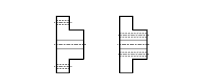 [!] Conditions may vary depending on the shaft bore specs. |
Shape A
 Shape B
 ·Hole Position  [!] Conditions may vary depending on the shaft bore specs. |
 ·Hole Position  [!] Conditions may vary depending on the shaft bore specs. | ||||||||||||||||||||||||||||||||||||||||||||||||||||||||||||||||


Part Number:
- In order to open the 3D preview, the part number must be fixed.
3D preview is not available, because the part number has not yet been determined.
| Part Number |
Standard Unit Price
| Minimum order quantity | Volume Discount | Number of Teeth (Teeth) | Twisting Direction | Surface Treatment | Shaft Bore Config. | Shaft Bore Dia., Shaft Dia. | Gear Shape | |
|---|---|---|---|---|---|---|---|---|---|---|
- | 1 | 7 Days | 15 | Right / Left | Black Oxide | Round hole+tap | 8 ~ 15 | Shape B | ||
- | 1 | 7 Days | 16 | Right / Left | Black Oxide | Round hole+tap | 8 ~ 16 | Shape B | ||
- | 1 | 7 Days | 17 | Right / Left | Black Oxide | Round hole+tap | 8 ~ 19 | Shape B | ||
- | 1 | 7 Days | 18 | Right / Left | Black Oxide | Round hole+tap | 8 ~ 21 | Shape B | ||
- | 1 | 7 Days | 19 | Right / Left | Black Oxide | Round hole+tap | 8 ~ 21 | Shape B | ||
- | 1 | 7 Days | 20 | Right / Left | Black Oxide | Round hole+tap | 8 ~ 23 | Shape B | ||
- | 1 | 7 Days | 21 | Right / Left | Black Oxide | Round hole+tap | 8 ~ 23 | Shape B | ||
- | 1 | 7 Days | 22 | Right / Left | Black Oxide | Round hole+tap | 8 ~ 25 | Shape B | ||
- | 1 | 7 Days | 23 | Right / Left | Black Oxide | Round hole+tap | 8 ~ 25 | Shape B | ||
- | 1 | 7 Days | 24 | Right / Left | Black Oxide | Round hole+tap | 8 ~ 28 | Shape B | ||
- | 1 | 7 Days | 25 | Right / Left | Black Oxide | Round hole+tap | 8 ~ 28 | Shape B | ||
- | 1 | 7 Days | 26 | Right / Left | Black Oxide | Round hole+tap | 8 ~ 30 | Shape B | ||
- | 1 | 7 Days | 27 | Right / Left | Black Oxide | Round hole+tap | 8 ~ 33 | Shape B | ||
- | 1 | 7 Days | 28 | Right / Left | Black Oxide | Round hole+tap | 8 ~ 33 | Shape B | ||
- | 1 | 7 Days | 29 | Right / Left | Black Oxide | Round hole+tap | 8 ~ 35 | Shape B | ||
- | 1 | 7 Days | 30 | Right / Left | Black Oxide | Round hole+tap | 8 ~ 36 | Shape B | ||
- | 1 | 7 Days | 32 | Right / Left | Black Oxide | Round hole+tap | 8 ~ 38 | Shape B | ||
- | 1 | 7 Days | 33 | Right / Left | Black Oxide | Round hole+tap | 8 ~ 38 | Shape B | ||
- | 1 | 7 Days | 34 | Right / Left | Black Oxide | Round hole+tap | 10 ~ 38 | Shape B | ||
- | 1 | 7 Days | 35 | Right / Left | Black Oxide | Round hole+tap | 10 ~ 40 | Shape B | ||
- | 1 | 7 Days | 36 | Right / Left | Black Oxide | Round hole+tap | 10 ~ 43 | Shape B | ||
- | 1 | 7 Days | 38 | Right / Left | Black Oxide | Round hole+tap | 10 ~ 43 | Shape B | ||
- | 1 | 7 Days | 39 | Right / Left | Black Oxide | Round hole+tap | 10 ~ 43 | Shape B | ||
- | 1 | 7 Days | 40 | Right / Left | Black Oxide | Round hole+tap | 10 ~ 48 | Shape B | ||
- | 1 | 7 Days | 42 | Right / Left | Black Oxide | Round hole+tap | 10 ~ 48 | Shape B | ||
- | 1 | 7 Days | 44 | Right / Left | Black Oxide | Round hole+tap | 10 ~ 48 | Shape B | ||
- | 1 | 7 Days | 45 | Right / Left | Black Oxide | Round hole+tap | 10 ~ 48 | Shape B | ||
- | 1 | 7 Days | 46 | Right / Left | Black Oxide | Round hole+tap | 10 ~ 48 | Shape B | ||
- | 1 | 7 Days | 48 | Right / Left | Black Oxide | Round hole+tap | 10 ~ 50 | Shape B | ||
- | 1 | 7 Days | 49 | Right / Left | Black Oxide | Round hole+tap | 10 ~ 50 | Shape B | ||
- | 1 | 7 Days | 50 | Right / Left | Black Oxide | Round hole+tap | 10 ~ 50 | Shape B | ||
- | 1 | 7 Days | 51 | Right / Left | Black Oxide | Round hole+tap | 12 ~ 52 | Shape B | ||
- | 1 | 7 Days | 52 | Right / Left | Black Oxide | Round hole+tap | 12 ~ 52 | Shape B | ||
- | 1 | 7 Days | 54 | Right / Left | Black Oxide | Round hole+tap | 12 ~ 52 | Shape B | ||
- | 1 | 7 Days | 55 | Right / Left | Black Oxide | Round hole+tap | 12 ~ 52 | Shape B | ||
- | 1 | 7 Days | 56 | Right / Left | Black Oxide | Round hole+tap | 12 ~ 52 | Shape B | ||
- | 1 | 7 Days | 57 | Right / Left | Black Oxide | Round hole+tap | 12 ~ 52 | Shape B | ||
- | 1 | 7 Days | 58 | Right / Left | Black Oxide | Round hole+tap | 12 ~ 52 | Shape B | ||
- | 1 | 7 Days | 60 | Right / Left | Black Oxide | Round hole+tap | 12 ~ 52 | Shape B | ||
- | 1 | 7 Days | 62 | Right / Left | Black Oxide | Round hole+tap | 15 ~ 52 | Shape B | ||
- | 1 | 7 Days | 63 | Right / Left | Black Oxide | Round hole+tap | 15 ~ 52 | Shape B | ||
- | 1 | 7 Days | 64 | Right / Left | Black Oxide | Round hole+tap | 15 ~ 52 | Shape B | ||
- | 1 | 7 Days | 65 | Right / Left | Black Oxide | Round hole+tap | 15 ~ 52 | Shape B | ||
- | 1 | 7 Days | 66 | Right / Left | Black Oxide | Round hole+tap | 15 ~ 52 | Shape B | ||
- | 1 | 7 Days | 68 | Right / Left | Black Oxide | Round hole+tap | 15 ~ 52 | Shape B | ||
- | 1 | 7 Days | 69 | Right / Left | Black Oxide | Round hole+tap | 15 ~ 52 | Shape B | ||
- | 1 | 7 Days | 70 | Right / Left | Black Oxide | Round hole+tap | 15 ~ 52 | Shape B | ||
- | 1 | 7 Days | 72 | Right / Left | Black Oxide | Round hole+tap | 15 ~ 52 | Shape B | ||
- | 1 | 7 Days | 75 | Right / Left | Black Oxide | Round hole+tap | 20 ~ 52 | Shape B | ||
- | 1 | 7 Days | 76 | Right / Left | Black Oxide | Round hole+tap | 20 ~ 52 | Shape B | ||
- | 1 | 7 Days | 77 | Right / Left | Black Oxide | Round hole+tap | 20 ~ 52 | Shape B | ||
- | 1 | 7 Days | 78 | Right / Left | Black Oxide | Round hole+tap | 20 ~ 52 | Shape B | ||
- | 1 | 7 Days | 80 | Right / Left | Black Oxide | Round hole+tap | 20 ~ 52 | Shape B | ||
- | 1 | 7 Days | 81 | Right / Left | Black Oxide | Round hole+tap | 20 ~ 55 | Shape B | ||
- | 1 | 7 Days | 84 | Right / Left | Black Oxide | Round hole+tap | 20 ~ 55 | Shape B | ||
- | 1 | 7 Days | 85 | Right / Left | Black Oxide | Round hole+tap | 20 ~ 55 | Shape B | ||
- | 1 | 7 Days | 88 | Right / Left | Black Oxide | Round hole+tap | 20 ~ 55 | Shape B | ||
- | 1 | 7 Days | 90 | Right / Left | Black Oxide | Round hole+tap | 20 ~ 55 | Shape B | ||
- | 1 | 7 Days | 91 | Right / Left | Black Oxide | Round hole+tap | 20 ~ 55 | Shape B | ||
- | 1 | 7 Days | 92 | Right / Left | Black Oxide | Round hole+tap | 20 ~ 55 | Shape B |
Loading...
| ·When selecting Keyway types, see the table on the right.  | ■New JIS (B1301) Keyway Dimensions
|
|
| |||||||||||||||||||||||||||||||||||||||||||||||||||||||||||||||||||||||||||||||||||||||||||||||||||||||||||||||||||||||||||||||||||||
Basic information
| Module | 2 | Environmentally Friendly | RoHS compliant (10 substances) | Properties / applications | Not Applicable |
|---|---|---|---|---|---|
| Material | EN 1.1191 Equiv. | Face Width(mm) | 20 |
Configure
Basic Attributes
-
Number of Teeth(Teeth)
-
Twisting Direction
- Right
- Left
-
Shaft Bore Config.
-
 Round Hole
 -
 Round hole+tap
 -
 Keyway
 -
 Keyway + Tap
-
-
Shaft Bore Dia., Shaft Dia.
-
Gear Shape
- Shape A
- Shape B
-
Type
- HGEARB
- HGEARBB
- HGEARBG
- HGEARHB
- HGEARHBB
- HGEARHBG
- HGEARKB
- HGEARKBB
- HGEARKBG
-
Surface Treatment
- Not Provided
- Black Oxide
- Electroless Nickel Plating
-
Filter by CAD data type
- 2D
- 3D


Filter by standard shipping days
-
- All
- 7 Days or Less
Optional Attributes
- The specifications and dimensions of some parts may not be fully covered. For exact details, refer to manufacturer catalogs .
Tech Support
Payment Method


On-Demand Manufacturing
Certificates


Copyright © MISUMI Corporation All Rights Reserved.