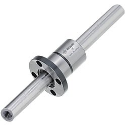
Ball Splines / Both Ends Tapped
Click on this image to zoom in.
Click on this image to zoom in.
(i)Remark
- Please check the content on our website as the PDF does not contain the most up-to-date information.

Part Number
Once your search is narrowed to one product,
the corresponding part number is displayed here.
- Drawing / Specifications
- 3D Preview 3D preview is available after complete configuration
- Part Numbers
- More Information
- Catalog
- Technical Information
Dimensional Drawing
 | Flange type nut orientation ● 1-Nut Type | ● 2-Nut Type |
 |  | |
| [ ! ] When selecting Overall Length (L Dimension), check the annealing range. | ||
| [ ! ] For the included nut, please select a shape from below. | ||
| ■Round Flanged |
 |
| ■Compact Flanged |
 |
| ■Straight Nuts | |
 | [A]Dimension of Included Key |
[ ! ] The key is press fit into the nut.
| One End Tapped | Spline Shaft [M] EN 1.3505 Equiv., Nut [M] EN 1.7242 Equiv. [H]Hardness: 58HRC or more | Spline Shaft and Nut [M] Material: EN 1.4125 Equiv. [H]Hardness: 55 HRC or more |
| Nut 1 pc. | Nut 1 pc. | |
| With Round Flange Nut | BSFM | BSFMS |
| With Compact Flange Nut | BSFN | — |
| With Straight Nut | BSFS | BSFSS |
[ ! ] Spline Shafts are hardened, and need to be annealed before machining.
[ ! ] As the accuracy is guaranteed as a set of nut and shaft, they are not sold separately.[ ! ] A dust-proof seal is attached to the nut, so the balls will not fall off even if the spline shaft is pulled out.
(If the spline shaft is inserted at an angle to the nut, the ball may fall out.)
Specification Table
| Part Number | — | L | — | M |
BSFS10 BSFS10G BSFS10G BSFS10L BSFS10L | — — — | 350 350 350 | — — — | M5 M5 M5 |
| Part Number | L: 1 mm Increments | M (Coarse) Selection | D | Mass (kg/m) | ||||||||
| Type | No. | 1-Nut Type | ||||||||||
| BSFM BSFN BSFS BSFMS BSFSS | * 6 | 60 to 500 (190) | 3 | 6 | 0.23 | |||||||
| * 8 | 60 to 600 (190) | 3 | 4 | 8 | 0.39 | |||||||
| * 10 | 60 to 800 (390) | 3 | 4 | 5 | 10.4 | 0.65 | ||||||
| * 13 | 60 to 800 (390) | 4 | 5 | 6 | 13.4 | 1.11 | ||||||
| * 16 | 70 to 1000 (390) | 4 | 5 | 6 | 8 | 16.6 | 1.65 | |||||
| 20 | 80 to 1000 | 5 | 6 | 8 | 10 | 20.6 | 2.57 | |||||
| 25 | 90 to 1300 | 5 | 6 | 8 | 10 | 12 | 25.8 | 4.04 | ||||
| 30 | 100 to 1300 | 6 | 8 | 10 | 12 | 16 | 30.8 | 5.85 | ||||
[ ! ] For BSFN, only No. 6, 8 and 10 are available.
[ ! ] Operating Temp.: Plastic components are used in ball spline assemblies. Avoid using in high temperature environments: keep below 80°C.
[ ! ] Lubrication: Ball splines are lubricated at the time of shipment, but should be re-lubricated after installation in equipment.
After you start using the vehicle, fill the grease every 100 km.
For re-lubrication, Lithium soap-based grease (Alvania Grease S2 by Showa Shell Sekiyu) is recommended.
| No. | D (h6) | L | df | H | P.C.D. | d1 | d2 | h | W | d | B | Basic Rated Torque | Basic Load Rating | Allowable Static Moment | Mass (kg) | |||
| Dynamic Ct (N⋅m) | Static C0 t (N⋅m) | Dynamic C (kN) | Static C0 (kN) | M01 (N⋅m) | M02 (N⋅m) | |||||||||||||
| 6 | 14 | 25 | 30 | 6 | 22 | 3.5 | 6 | 3.1 | 6.5 | 1.5 | 18 | 3.8 | 7 | 1.2 | 2.1 | 5 | 36 | 0.03 |
| 8 | 16 | 32 | 24 | 21 | 4.8 | 8.7 | 1.2 | 2.1 | 5 | 36 | 0.04 | |||||||
| 10 | 21 | 40 (33) | 42 (41) | 6 (8) | 32 (30) | 4.5 | 8 | 4.4 (5.3) | 14 (8.5) | 25 | 19 (11) | 34 (21) | 3.8 (2.4) | 6.9 (4.3) | 26 (15) | 181 (102) | 0.09 | |
| 13 | 24 | 44 (36) | 44 (45) | 7 (8) | 33 (34) | 15 (10) | — | 28 (20) | 52 (37) | 4.6 (3.3) | 8.3 (5.9) | 36 (22) | 251 (148) | 0.11 | ||||
| 16 | 31 | 50 | 51 | 7 | 40 | 4.4 | 18 | 51 | 93 | 6.2 | 11.1 | 56 | 386 | 0.2 | ||||
| 20 | 35 | 63 | 58 | 9 | 45 | 5.5 | 9.5 | 5.4 | 22.5 | 2 | 85 | 154 | 8.5 | 15.3 | 83 | 611 | 0.3 | |
| 25 | 42 | 71 | 65 | 52 | 26.5 | 193 | 348 | 15.4 | 27.7 | 173 | 1248 | 0.4 | ||||||
| 30 | 47 | 80 | 75 | 10 | 60 | 6.6 | 11 | 6.5 | 30 | 2.5 | 272 | 490 | 18.5 | 33.3 | 212 | 1581 | 0.57 | |
| No. | D (h6) | L | b | t (+0.05 0) | d | α | Basic Rated Torque | Basic Load Rating | Allowable Static Moment | Mass (kg) | Dimensions of Key (Included) | |||||||||
| Tolerance | Dynamic Ct (N⋅m) | Static C0 t (N⋅m) | Dynamic C (kN) | Static C0 (kN) | M01 (N⋅m) | M02 (N⋅m) | B | h | L1 | R | ||||||||||
| Tolerance | Tolerance | |||||||||||||||||||
| 6 | 14 | 25 | 2.5 | +0.014 0 | 1.2 | 1.5 | 15° | 3.8 | 7 | 1.2 | 2.1 | 5 | 36 | 0.012 | 2.5 | +0.016 +0.006 | 2.5 | 0 −0.025 | 10.5 | 1.25 |
| 8 | 16 | 25° | 4.8 | 8.7 | 1.2 | 2.1 | 5 | 36 | 0.013 | 10.5 | ||||||||||
| 10 | 21 | 40 (33) | 3 | 1.5 | — | 19 (11) | 34 (21) | 3.8 (2.4) | 6.9 (4.3) | 26 (15) | 181 (102) | 0.06 | 3 | 3 | 17 (14) | 1.5 | ||||
| 13 | 24 | 44 (36) | 28 (20) | 52 (37) | 4.6 (3.3) | 8.3 (5.9) | 36 (22) | 251 (148) | 0.07 | 17 (14) | ||||||||||
| 16 | 31 | 50 | 3.5 | +0.018 0 | 2 | 51 | 93 | 6.2 | 11.1 | 56 | 386 | 0.15 | 3.5 | +0.024 +0.012 | 3.5 | 0 −0.030 | 18 | 1.75 | ||
| 20 | 35 | 63 | 4 | 2.5 | 2 | 85 | 154 | 8.5 | 15.3 | 83 | 611 | 0.2 | 4 | 4 | 29 | 2 | ||||
| 25 | 42 | 71 | 193 | 348 | 15.4 | 27.7 | 173 | 1248 | 0.29 | 33 | ||||||||||
| 30 | 47 | 80 | 2.5 | 272 | 490 | 18.5 | 33.3 | 212 | 1581 | 0.37 | 42 | |||||||||
Alterations
| Part Number | — | L | — | M | — | (SC·FC·NTW) |
| BSFS10 | — | 350 | — | M5 | — | SC15 |
| Alterations | Wrench Flats | Set Screw Flat | Additional Spline Nuts | |||||||||||||||||||||||||||||||||||||||
 |  |  | ||||||||||||||||||||||||||||||||||||||||
| Code | SC | FC | NTW | |||||||||||||||||||||||||||||||||||||||
| Spec. |
|
| Adds a nut. (from one to two) [ ! ] BSFS·BSFM Applicable to BSFN only | |||||||||||||||||||||||||||||||||||||||
[ ! ] The angles / positions of alterations such as wrench flats, set screw flat, and keyway are not on the same plane.
[ ! ] It is not possible to specify the key of the spline nut or the positional relationship between the mounting hole and alteration.
Part Number:
- In order to open the 3D preview, the part number must be fixed.
3D preview is not available, because the part number has not yet been determined.
| Part Number | Minimum order quantity | Volume Discount | RoHS | Nut type | Shaft O.D. D (φ) | Shaft material | Nut Overall Length (mm) | Nut O.D. (φ) | Shaft Overall Length L (mm) | Basic Load Rating Dynamic Rating (N) | Allowable Torque (Nm) | Nut Material | Grease | M (mm) | |
|---|---|---|---|---|---|---|---|---|---|---|---|---|---|---|---|
| 1 | 10 Days | 10 | [Flange Type] Round Flanged | 6 | EN 1.3505 Equiv. | 25 | 14 | 60 ~ 400 | 1200 | 3.8 | EN 1.7242 Equiv. | Standard (S2) | 3 | ||
| 1 | 12 Days | 10 | [Flange Type] Round Flanged | 6 | EN 1.3505 Equiv. | 25 | 14 | 60 ~ 400 | 1200 | 3.8 | EN 1.7242 Equiv. | LG2 | 3 | ||
| 1 | 12 Days | 10 | [Flange Type] Round Flanged | 6 | EN 1.3505 Equiv. | 25 | 14 | 60 ~ 400 | 1200 | 3.8 | EN 1.7242 Equiv. | ET-100K | 3 | ||
| 1 | 10 Days | 10 | [Flange Type] Round Flanged | 8 | EN 1.3505 Equiv. | 25 | 16 | 60 ~ 400 | 1200 | 4.8 | EN 1.7242 Equiv. | Standard (S2) | 3 ~ 4 | ||
| 1 | 12 Days | 10 | [Flange Type] Round Flanged | 8 | EN 1.3505 Equiv. | 25 | 16 | 60 ~ 400 | 1200 | 4.8 | EN 1.7242 Equiv. | LG2 | 3 ~ 4 | ||
| 1 | 12 Days | 10 | [Flange Type] Round Flanged | 8 | EN 1.3505 Equiv. | 25 | 16 | 60 ~ 400 | 1200 | 4.8 | EN 1.7242 Equiv. | ET-100K | 3 ~ 4 | ||
| 1 | 10 Days | 10 | [Flange Type] Round Flanged | 10.4 | EN 1.3505 Equiv. | 40 | 21 | 60 ~ 600 | 3800 | 19 | EN 1.7242 Equiv. | Standard (S2) | 3 ~ 5 | ||
| 1 | 12 Days | 10 | [Flange Type] Round Flanged | 10.4 | EN 1.3505 Equiv. | 40 | 21 | 60 ~ 600 | 3800 | 19 | EN 1.7242 Equiv. | LG2 | 3 ~ 5 | ||
| 1 | 12 Days | 10 | [Flange Type] Round Flanged | 10.4 | EN 1.3505 Equiv. | 40 | 21 | 60 ~ 600 | 3800 | 19 | EN 1.7242 Equiv. | ET-100K | 3 ~ 5 | ||
| 1 | 10 Days | 10 | [Flange Type] Round Flanged | 13.4 | EN 1.3505 Equiv. | 44 | 24 | 60 ~ 600 | 4600 | 28 | EN 1.7242 Equiv. | Standard (S2) | 4 ~ 6 | ||
| 1 | 12 Days | 10 | [Flange Type] Round Flanged | 13.4 | EN 1.3505 Equiv. | 44 | 24 | 60 ~ 600 | 4600 | 28 | EN 1.7242 Equiv. | LG2 | 4 ~ 6 | ||
| 1 | 12 Days | 10 | [Flange Type] Round Flanged | 13.4 | EN 1.3505 Equiv. | 44 | 24 | 60 ~ 600 | 4600 | 28 | EN 1.7242 Equiv. | ET-100K | 4 ~ 6 | ||
| 1 | 10 Days | 10 | [Flange Type] Round Flanged | 16.6 | EN 1.3505 Equiv. | 50 | 31 | 70 ~ 600 | 6200 | 51 | EN 1.7242 Equiv. | Standard (S2) | 4 ~ 8 | ||
| 1 | 12 Days | 10 | [Flange Type] Round Flanged | 16.6 | EN 1.3505 Equiv. | 50 | 31 | 70 ~ 600 | 6200 | 51 | EN 1.7242 Equiv. | LG2 | 4 ~ 8 | ||
| 1 | 12 Days | 10 | [Flange Type] Round Flanged | 16.6 | EN 1.3505 Equiv. | 50 | 31 | 70 ~ 600 | 6200 | 51 | EN 1.7242 Equiv. | ET-100K | 4 ~ 8 | ||
| 1 | 10 Days | 10 | [Flange Type] Round Flanged | 20.6 | EN 1.3505 Equiv. | 63 | 35 | 80 ~ 700 | 8500 | 85 | EN 1.7242 Equiv. | Standard (S2) | 5 ~ 10 | ||
| 1 | 12 Days | 10 | [Flange Type] Round Flanged | 20.6 | EN 1.3505 Equiv. | 63 | 35 | 80 ~ 700 | 8500 | 85 | EN 1.7242 Equiv. | LG2 | 5 ~ 10 | ||
| 1 | 12 Days | 10 | [Flange Type] Round Flanged | 20.6 | EN 1.3505 Equiv. | 63 | 35 | 80 ~ 700 | 8500 | 85 | EN 1.7242 Equiv. | ET-100K | 5 ~ 10 | ||
| 1 | 10 Days | 10 | [Flange Type] Round Flanged | 25.8 | EN 1.3505 Equiv. | 71 | 42 | 90 ~ 1300 | 15400 | 193 | EN 1.7242 Equiv. | Standard (S2) | 5 ~ 12 | ||
| 1 | 12 Days | 10 | [Flange Type] Round Flanged | 25.8 | EN 1.3505 Equiv. | 71 | 42 | 90 ~ 900 | 15400 | 193 | EN 1.7242 Equiv. | LG2 | 5 ~ 12 | ||
| 1 | 12 Days | 10 | [Flange Type] Round Flanged | 25.8 | EN 1.3505 Equiv. | 71 | 42 | 90 ~ 900 | 15400 | 193 | EN 1.7242 Equiv. | ET-100K | 5 ~ 12 | ||
| 1 | 10 Days | 10 | [Flange Type] Round Flanged | 30.8 | EN 1.3505 Equiv. | 80 | 47 | 100 ~ 1150 | 18500 | 272 | EN 1.7242 Equiv. | Standard (S2) | 6 ~ 16 | ||
| 1 | 12 Days | 10 | [Flange Type] Round Flanged | 30.8 | EN 1.3505 Equiv. | 80 | 47 | 100 ~ 1150 | 18500 | 272 | EN 1.7242 Equiv. | LG2 | 6 ~ 16 | ||
| 1 | 12 Days | 10 | [Flange Type] Round Flanged | 30.8 | EN 1.3505 Equiv. | 80 | 47 | 100 ~ 1150 | 18500 | 272 | EN 1.7242 Equiv. | ET-100K | 6 ~ 16 | ||
| 1 | 9 Days | 10 | [Flange Type] Round Flanged | 6 | EN 1.4125 Equiv. | 25 | 14 | 60 ~ 190 | 1200 | 3.8 | EN 1.4125 Equiv. | Standard (S2) | 3 | ||
| 1 | 11 Days | 10 | [Flange Type] Round Flanged | 6 | EN 1.4125 Equiv. | 25 | 14 | 60 ~ 190 | 1200 | 3.8 | EN 1.4125 Equiv. | LG2 | 3 | ||
| 1 | 11 Days | 10 | [Flange Type] Round Flanged | 6 | EN 1.4125 Equiv. | 25 | 14 | 60 ~ 190 | 1200 | 3.8 | EN 1.4125 Equiv. | ET-100K | 3 | ||
| 1 | 9 Days | 10 | [Flange Type] Round Flanged | 8 | EN 1.4125 Equiv. | 25 | 16 | 60 ~ 190 | 1200 | 4.8 | EN 1.4125 Equiv. | Standard (S2) | 3 ~ 4 | ||
| 1 | 11 Days | 10 | [Flange Type] Round Flanged | 8 | EN 1.4125 Equiv. | 25 | 16 | 60 ~ 190 | 1200 | 4.8 | EN 1.4125 Equiv. | LG2 | 3 ~ 4 | ||
| 1 | 11 Days | 10 | [Flange Type] Round Flanged | 8 | EN 1.4125 Equiv. | 25 | 16 | 60 ~ 190 | 1200 | 4.8 | EN 1.4125 Equiv. | ET-100K | 3 ~ 4 | ||
| 1 | 9 Days | 10 | [Flange Type] Round Flanged | 10.4 | EN 1.4125 Equiv. | 33 | 21 | 60 ~ 390 | 2400 | 11 | EN 1.4125 Equiv. | Standard (S2) | 3 ~ 5 | ||
| 1 | 11 Days | 10 | [Flange Type] Round Flanged | 10.4 | EN 1.4125 Equiv. | 33 | 21 | 60 ~ 390 | 2400 | 11 | EN 1.4125 Equiv. | LG2 | 3 ~ 5 | ||
| 1 | 11 Days | 10 | [Flange Type] Round Flanged | 10.4 | EN 1.4125 Equiv. | 33 | 21 | 60 ~ 390 | 2400 | 11 | EN 1.4125 Equiv. | ET-100K | 3 ~ 5 | ||
| 1 | 9 Days | 10 | [Flange Type] Round Flanged | 13.4 | EN 1.4125 Equiv. | 36 | 24 | 60 ~ 390 | 3300 | 20 | EN 1.4125 Equiv. | Standard (S2) | 4 ~ 6 | ||
| 1 | 11 Days | 10 | [Flange Type] Round Flanged | 13.4 | EN 1.4125 Equiv. | 36 | 24 | 60 ~ 390 | 3300 | 20 | EN 1.4125 Equiv. | LG2 | 4 ~ 6 | ||
| 1 | 11 Days | 10 | [Flange Type] Round Flanged | 13.4 | EN 1.4125 Equiv. | 36 | 24 | 60 ~ 390 | 3300 | 20 | EN 1.4125 Equiv. | ET-100K | 4 ~ 6 | ||
| 1 | 9 Days | 10 | [Flange Type] Round Flanged | 16.6 | EN 1.4125 Equiv. | 50 | 31 | 70 ~ 390 | 6200 | 51 | EN 1.4125 Equiv. | Standard (S2) | 4 ~ 8 | ||
| 1 | 11 Days | 10 | [Flange Type] Round Flanged | 16.6 | EN 1.4125 Equiv. | 50 | 31 | 70 ~ 390 | 6200 | 51 | EN 1.4125 Equiv. | LG2 | 4 ~ 8 | ||
| 1 | 11 Days | 10 | [Flange Type] Round Flanged | 16.6 | EN 1.4125 Equiv. | 50 | 31 | 70 ~ 390 | 6200 | 51 | EN 1.4125 Equiv. | ET-100K | 4 ~ 8 | ||
| 1 | 10 Days | 10 | [Flange Type] Compact Flanged | 6 | EN 1.3505 Equiv. | 25 | 14 | 60 ~ 400 | 1200 | 3.8 | EN 1.7242 Equiv. | Standard (S2) | 3 | ||
| 1 | 12 Days | 10 | [Flange Type] Compact Flanged | 6 | EN 1.3505 Equiv. | 25 | 14 | 60 ~ 400 | 1200 | 3.8 | EN 1.7242 Equiv. | LG2 | 3 | ||
| 1 | 12 Days | 10 | [Flange Type] Compact Flanged | 6 | EN 1.3505 Equiv. | 25 | 14 | 60 ~ 400 | 1200 | 3.8 | EN 1.7242 Equiv. | ET-100K | 3 | ||
| 1 | 10 Days | 10 | [Flange Type] Compact Flanged | 8 | EN 1.3505 Equiv. | 25 | 16 | 60 ~ 400 | 1200 | 4.8 | EN 1.7242 Equiv. | Standard (S2) | 3 ~ 4 | ||
| 1 | 12 Days | 10 | [Flange Type] Compact Flanged | 8 | EN 1.3505 Equiv. | 25 | 16 | 60 ~ 400 | 1200 | 4.8 | EN 1.7242 Equiv. | LG2 | 3 ~ 4 | ||
| 1 | 12 Days | 10 | [Flange Type] Compact Flanged | 8 | EN 1.3505 Equiv. | 25 | 16 | 60 ~ 400 | 1200 | 4.8 | EN 1.7242 Equiv. | ET-100K | 3 ~ 4 | ||
| 1 | 10 Days | 10 | [Flange Type] Compact Flanged | 10.4 | EN 1.3505 Equiv. | 40 | 21 | 60 ~ 600 | 3800 | 19 | EN 1.7242 Equiv. | Standard (S2) | 3 ~ 5 | ||
| 1 | 12 Days | 10 | [Flange Type] Compact Flanged | 10.4 | EN 1.3505 Equiv. | 40 | 21 | 60 ~ 600 | 3800 | 19 | EN 1.7242 Equiv. | LG2 | 3 ~ 5 | ||
| 1 | 12 Days | 10 | [Flange Type] Compact Flanged | 10.4 | EN 1.3505 Equiv. | 40 | 21 | 60 ~ 600 | 3800 | 19 | EN 1.7242 Equiv. | ET-100K | 3 ~ 5 |
Loading...
Specifications/Overview
| Precautions for Ball Spline Assembly |  |
| ■Check Assembly Position | |
| Match Mark Numbers are entered on nuts and spline shafts (see the diagram on the right). | |
| When re-assembling, confirm the match mark numbers, character orientations, and positional relationship of parts. | |
| If the alignment marks are not aligned correctly, the function will be affected. | |
| ■Tolerance for Mating Bores | |
| H7 tolerance is recommended for mating bores for the spline nuts when mounting them on housings. | |
| ■For Customers machining the shaft ends | |
| In order to facilitate nut insertions, chamfer the machined shaft ends, and remove burrs on the edges of the spline groove with a round file. |
Basic information
| Shaft end shape (left) | Tapped | Shaft end shape (right) | Standard | Type | Solid |
|---|---|---|---|---|---|
| Torque | Middle Torque | Number of nuts(pcs.) | 1 | Nut length | Standard |
| Preload | Standard | Accuracy Grade | Standard Grade | The circulation type of balls | 1-fach |
Configure
Basic Attributes
-
Shaft O.D. D(φ)
-
Shaft material
- EN 1.3505 Equiv.
- EN 1.4125 Equiv.
-
Nut Overall Length(mm)
-
Nut O.D.(φ)
-
Shaft Overall Length L(mm)
-
Nut Material
- EN 1.4125 Equiv.
- EN 1.7242 Equiv.
-
Grease
- ET-100K
- LG2
- Standard (S2)
-
M(mm)
-
Type
- BSFM
- BSFMS
- BSFN
- BSFS
- BSFSS
-
Nut type
- Straight
- Flange Type
-
Filter by CAD data type
- 2D
- 3D
Filter by standard shipping days
-
- All
- 9 Days or Less
- 10 Days or Less
- 11 Days or Less
- 12 Days or Less
Optional Attributes
- The specifications and dimensions of some parts may not be fully covered. For exact details, refer to manufacturer catalogs .
Complementary Products


MISUMI Unit еxample related to this product


Tech Support
- Technical Support
- Tel:+49 69 668173-0 / FAX:+49 69 668173-360
- Technical Inquiry
Payment Method


On-Demand Manufacturing
Certificates


Copyright © MISUMI Corporation All Rights Reserved.