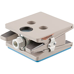
Leveling Mounts (Part Numbers - CAD Download)


Part Number
Once your search is narrowed to one product,
the corresponding part number is displayed here.
- Drawing / Specifications
- 3D Preview 3D preview is available after complete configuration
- Part Numbers
- More Information
- Catalog

W/O Stabilizer
With Stabilizer
KHWM-C
(W/O Pad)
KHWM-SC
(W/O Pad)
* For KHWM-C47, M16 × 12 on the bottom surface
* For KHWM-SC56, M16 × 12 on the bottom surface
KHWM-P
(With Pad)
KHWM-SP
(With Pad)
* For KHWM-P52, M16 × 12 on the bottom surface
* For KHWM-SP61, M16 × 12
| Type | Main Body | Adjusting Bolt | Stabilizer | Rubber | ||||
| Material | Surface Treatment | Material | Surface Treatment | Material | Surface Treatment | Material (Color) | Hardness | |
| KHWM−C | Grey Casting Ductile | Baked Finish | EN 1.1191 Equiv. | Electrolytic Zinc Plating | - | - | - | - |
| KHWM−P | Nitrile Rubber (Blue) | Shore A95 | ||||||
| KHWM−SC | EN 1.0038 Equiv. | Electrolytic Zinc Plating | - | - | ||||
| KHWM−SP | Nitrile Rubber (Blue) | Shore A95 | ||||||
Specification Table
| Part Number |
| KHWM−SC56 |
| Type | Part Number | A | C | H | h1 | h2 | Y | E | F | Adjusting Bolt Dimension | Stabilizer | Pad | Allowable Vertical Load (kN) | Height Adjustment Amount (mm) | Level Accuracy (mm/1 rotation) | Inclination Adjustable Angle | Mass (kg) | |||||
| Type | H | B | b | D | d | W | V | |||||||||||||||
| W/O Stabilizer | W/O Pad | KHWM−C | 47 | 110 | 115 | 47 | 41 | 53 | 20 | 64 | 51 | 22 | 12 | — | — | — | — | 50 | ±6 | 0.24 | — | 3.3 |
| 51 | 130 | 140 | 51 | 45 | 57 | 74 | 66 | 70 | 5.4 | |||||||||||||
| With Pad | KHWM−P | 52 | 110 | 115 | 52 | 46 | 58 | 64 | 51 | 111 | 106 | 16 | 3.4 | |||||||||
| 56 | 130 | 140 | 56 | 50 | 62 | 74 | 66 | 136 | 126 | 25 | 5.5 | |||||||||||
| With Stabilizer | W/O Pad | KHWM−SC | 56 | 110 | 115 | 56 | 50 | 62 | 20 | 64 | 51 | 22 | 12 | 108 | 78 | — | — | 50 | ±3° | 3.6 | ||
| 62 | 130 | 140 | 62 | 56 | 68 | 74 | 66 | 70 | 6.0 | |||||||||||||
| With Pad | KHWM−SP | 61 | 110 | 115 | 61 | 55 | 67 | 64 | 51 | 111 | 106 | 16 | 3.7 | |||||||||
| 67 | 130 | 140 | 67 | 61 | 73 | 74 | 66 | 136 | 126 | 25 | 6.1 | |||||||||||
Part Number:
- In order to open the 3D preview, the part number must be fixed.
3D preview is not available, because the part number has not yet been determined.
Part Number
|
|---|
| KHWM-C47 |
| KHWM-C51 |
| KHWM-P52 |
| KHWM-P56 |
| KHWM-SC56 |
| KHWM-SC62 |
| KHWM-SP61 |
| KHWM-SP67 |
| Part Number |
Standard Unit Price
| Minimum order quantity | Volume Discount | RoHS | Stabilizers | Pad | Standard Height H | |
|---|---|---|---|---|---|---|---|---|
304.70 € | 1 | Available | 29 Days | 10 | Not Provided | Not Provided | 47 | |
333.06 € | 1 | Available | 29 Days | 10 | Not Provided | Not Provided | 51 | |
347.29 € | 1 | Available | 6 Days | 10 | Not Provided | Provided | 52 | |
381.13 € | 1 | Available | 6 Days | 10 | Not Provided | Provided | 56 | |
330.87 € | 1 | Available | 6 Days | 10 | Provided | Not Provided | 56 | |
360.32 € | 1 | Available | 29 Days | 10 | Provided | Not Provided | 62 | |
373.46 € | 1 | Available | 29 Days | 10 | Provided | Provided | 61 | |
408.39 € | 1 | Available | 29 Days | 10 | Provided | Provided | 67 |
Loading...
Specifications/Overview
·This leveling mount enables installation and height adjustment of devices and apparatuses due to the effect of integrated special springs.
·Because the adjusting bolt head will not move back and forth during leveling adjustment, this will improve your work efficiency.
·Low particle generation fluorinated grease is applied to Standard Type, which is suitable for clean environments. (Clean Room Class is not guaranteed.)
·With Pad Type has an attenuation effect for self-induced vibration. Also excels in oil resistance and antitransitivity (color transfer to the floor).
·The "With Stabilizer" Type supports the floor inclination (±3°) environments to keep the device horizontal, which ensures stable work environments.
| Item | Unit | HDR Rubber |
| Hardness | Shore A | 95 |
| Specific Gravity | — | 1.25 |
| Tensile Strength | MPa | 6.5 |
| Elongation | % | 100 |
| Max. Operating Temperature | °C | 80 |
| Continuous Use Temperature | °C | 70 |
| Cold Resistance | °C | 0 |
| Name | Item | Contained Amount | Unit | Measurement Method | Conditions |
| Fluorinated Resin | Thickener | — | — | — | — |
| Per-Fluoro Polyether Oil | Base Oil | — | — | — | — |
| Dropping Point | None | — | JIS K−2220 5·4 | — | |
| Evaporation Amount | ≤ 0.2 | mass% | Proprietary scheme | 200°C, 24 h | |
| Oil Separation | ≤ 10 | mass% | Proprietary scheme | ||
| mass% | |||||
| mass% | |||||

Working equipment Working equipment

Horizontal floor Floor 3° inclination
·FPD Manufacturing Processor
·Semiconductor Manufacturing Processor
·Precision Metal Processor
·Large Precision Measuring Instrument
·Other Devices and Apparatuses
| Part Number | How to Mount | Mounting Height H | Selected Bolt | |||
| Screw-In Depth (Overall Depth) | Base Thickness | Nut | Washer | |||
| LBNR16− | FWS16− | RCB16− | ||||
| P.276 | P.147 | P.224 | ||||
| KHWM−P52 | Device Mounting | 53 | Arbitrary | 13 | 2.5 | RCB16- L Dimension |
| KHWM−P56 | 57 | |||||
| KHWM−SP61 | 62 | |||||
| KHWM−SP67 | 68 | |||||
| KHWM−C47 | 53 | |||||
| KHWM−C51 | 57 | |||||
| KHWM−SC56 | 62 | |||||
| KHWM−SC62 | 68 | |||||
·Customers are to provide anchor mounting bolts. Please provide M16 (Coarse).
·Length of anchor bolts ≥ device flange/frame thickness + depth of screwed-in leveling mount (total depth) + hex nut and plain washer thickness.
·Anchor bolt mounting holes can be ignored when not necessary.
(1) The flange, frame and the floor of the device on which leveling mounts are to be mounted require adequate rigidity.
(2) Place a device gently onto the leveling mount.
(3) When mounting a leveling mount on the device with bolts, align the mounting holes of the device and the tap position of the leveling mounts.
Next, insert a hex bolt, a hex nut and a plain washer into a mounting hole of the device and screw them in the tap hole of the leveling mount.
Do not tighten the hex nut at this point. (Hex bolts, hex nuts and plain washers are supplied by users.)
After level adjustment 5 is complete, tighten hex nuts and plain washers. At this time, if the supporting load is very light,
the body of the leveling mount may tilt due to over-tightening of the nut. Be careful not to overtighten.
(4) Turn the hex head (hole) on the front side of the leveling mount by a tool and adjust the level of the device.
Turn clockwise to increase the level and counterclockwise to decrease the level.
(5) Adjust each leveling mount gradually to avoid load concentration on the leveling mount.


Please be sure to use within the leveling adjustment range (±6 mm) as shown in the table above.
1 mm clearance at part A should be remained for the minimum height.
This clearance is to avoid interference between the slide groove and the slide fixing bracket.
Note that if the level is lower, the casted main body will be in contact and the slide fixing bracket will come off from the slide groove, which will cause damage or breakage.
For the maximum height, the tip of the middle part slides to the side edge of the upper/lower part for A130 and C140, while it slides to the edge of the leveling bolt for A110 and C115.
Do not increase the height further.
 |  |  |
| Min. Height | Min. Height | Max. Height |
 |  |  |
| Min. Height | Min. Height | Max. Height |
 |  |

[ ! ] Jack up the device at a certain height previously, install the leveling mounts,
and make a final adjustment using leveling mounts.
[ ! ] The middle part (wedge shape) moves back and forth when adjusting the level.
Keep 30 mm clearance in back of the leveling mounts.
[ ! ] Please pay close attention to safety measures.
Configure
Basic Attributes
-
Stabilizers
- Not Provided
- Provided
-
Pad
- Not Provided
- Provided
-
Standard Height H
- 47
- 51
- 52
- 56
- 61
- 62
- 67
-
Type
- KHWM-C
- KHWM-P
- KHWM-SC
- KHWM-SP
-
Filter by CAD data type
- 2D
- 3D
Filter by standard shipping days
-
- All
- 6 Days or Less
- 29 Days or Less
Optional Attributes
- The specifications and dimensions of some parts may not be fully covered. For exact details, refer to manufacturer catalogs .
Complementary Products


Tech Support
Payment Method


On-Demand Manufacturing
Certificates


Copyright © MISUMI Corporation All Rights Reserved.